Savant Power & Light App - Initial Smart Panel Configuration
| Document Date: | December 2025 (Updated) |
| Document Supports: | SP&L Version 3.3.2 and higher |
| Power Modules Version 3.5 and Higher |
Overview
The Savant Power & Light (SP&L) app, available for iOS and Android, allows for streamlined configuration of Savant Power system components, including the Savant Power Director, Savant Power Modules, and associated devices including Savant Power Storage 20 / 50, supported 3rd party energy storage systems, Savant EV Chargers, GE Smart Thermostats, GE Smart Water Heaters, and more.
This document guides installers through the initial configuration of a Savant Smart Panel (Power Director and Power Modules) using the SP&L app. Topics include creating a Home, adding power system devices, configuring panels, Power Modules, and breakers, creating Energy Scenes, and syncing the final configuration to the Director.
Additionally, this guide presents direct links to in-depth articles covering other (optional, system design dependent) aspects of Savant Power System deployment and configuration using the SP&L app, including:
- Adding and Configuring Smart Energy Monitor (SEM-2015 Only) System
- Adding and Configuring a GE Smart Thermostat
- Adding and Configuring a GE Smart Water Heater
- Adding and Configuring a Savant EV Charger
- Software and Device Firmware Update Procedures
- Adding Power Sources
- Power Module Information
1. Before Beginning
Documentation
Before completing the sections listed in this guide, it is important to understand its place within the Savant Power ecosystem. This and all linked articles within the portal cover the Configuration phase of Savant Power System installation, using the Savant Power & Light app. This document assumes that the reader has read all documentation associated with the equipment in use, has installed all equipment correctly, and has access to the breaker panel to be configured. Refer to the Getting Started - Installer Guide article on the Savant Power support site, or the Savant Power System Documentation Portal on the Savant Customer Community for additional deployment documents relevant to the equipment being installed.
If an integrated energy storage system (ESS) is in use, review the Savant Power & Light App (SP&L) - Adding Power Sources article and ensure that all components are installed and configured as documented before adding them to the system via SP&L.
Smart Panel - Required Products
The following items are required for deploying a Savant Smart Panel system using the Savant Power & Light app:
- Savant Power Director (HST-DIRECTOR)
- iOS or Android device
- Savant Power & Light app (downloaded via the iOS App Store or the Google Play Store)
- Savant Power Modules (Version 3.5 and higher)
Additional Products (Optional)
Additional components may also be incorporated depending on individual system design and specifications. These devices must also be added and configured using the Savant Power & Light app if in use:
- Savant Power Storage (PS20 or PS50 with Savant Power Inverter)
- Supported 3rd party energy storage systems (ESS)
- Savant EV Charger
- GE Smart Thermostat
- GE Smart Water Heater
- Savant Panel Bridge (PBC-P1000 or PB-P2000)
- Savant Smart Energy Monitor (SEM-2015)
- Savant Current Track Modules and CTs
Director Installation
The Director must be mounted, connected to the network, and powered on before proceeding with deployment. Refer to the Savant Power Director Quick Reference Guide for further installation details.
- Mount the Director in a location chosen during the design phase within 8-10 feet of the electrical panel.
- (DIRECTOR-00 ONLY) Screw in the Wi-Fi and Bluetooth antennas to the SMA connector ports.
- The Savant Power Director communicates over IP. Connect the Director to the network switch using a CAT cable.
- For wireless network use, refer to Provision the Director to Wi-Fi below.
- (Optional) Connect the Director to an uninterruptible power supply (UPS).
Provision the Director to Wi-Fi (Optional)
Homes using a wireless connection for Director communication require the iOS or Android device to join the same Wi-Fi network that the Director will use. The Savant Power & Light app automatically scans the network for available Savant devices.
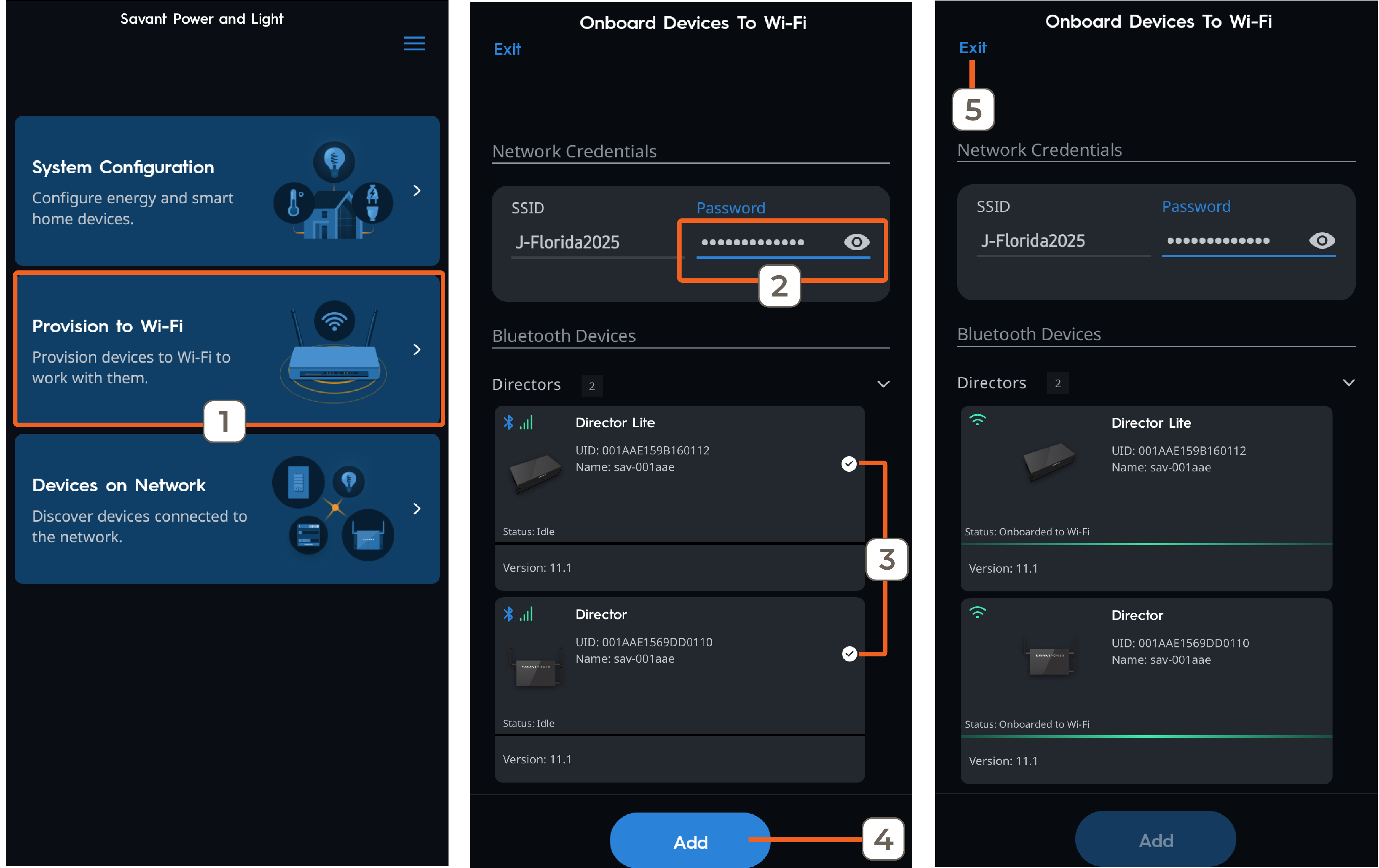
Follow the steps below to provision the Director to Wi-Fi:
- Tap Provision to Wi-Fi.
- Enter the SSID password.
- Select the devices to provision (multiple devices can be added simultaneously).
- Tap Add.
- After the devices connect to the network, tap Exit.
2. Module Setup
Follow the steps below to program the Power Modules after physical installation.
Module Data consists of three parts:
| Spaces | The starting space a Power Module occupies within the breaker panel. |
| Room Name | The name of the room to which the circuit provides power. |
| Circuit Name | Name of each circuit controlled by its respective Power Module Channel. |
| CT Size | (Current Track Modules Only) The rated amperage of the connected current transformer (CT). |
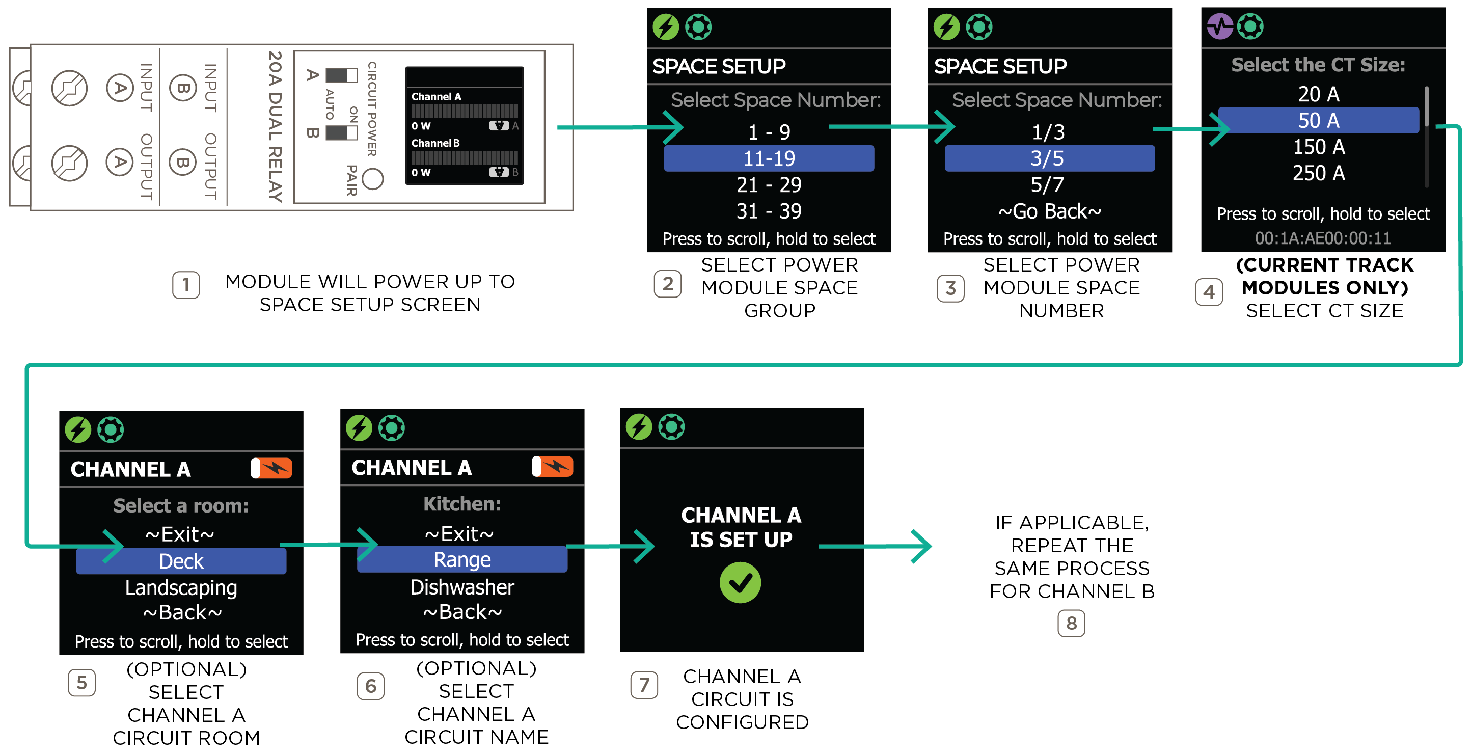
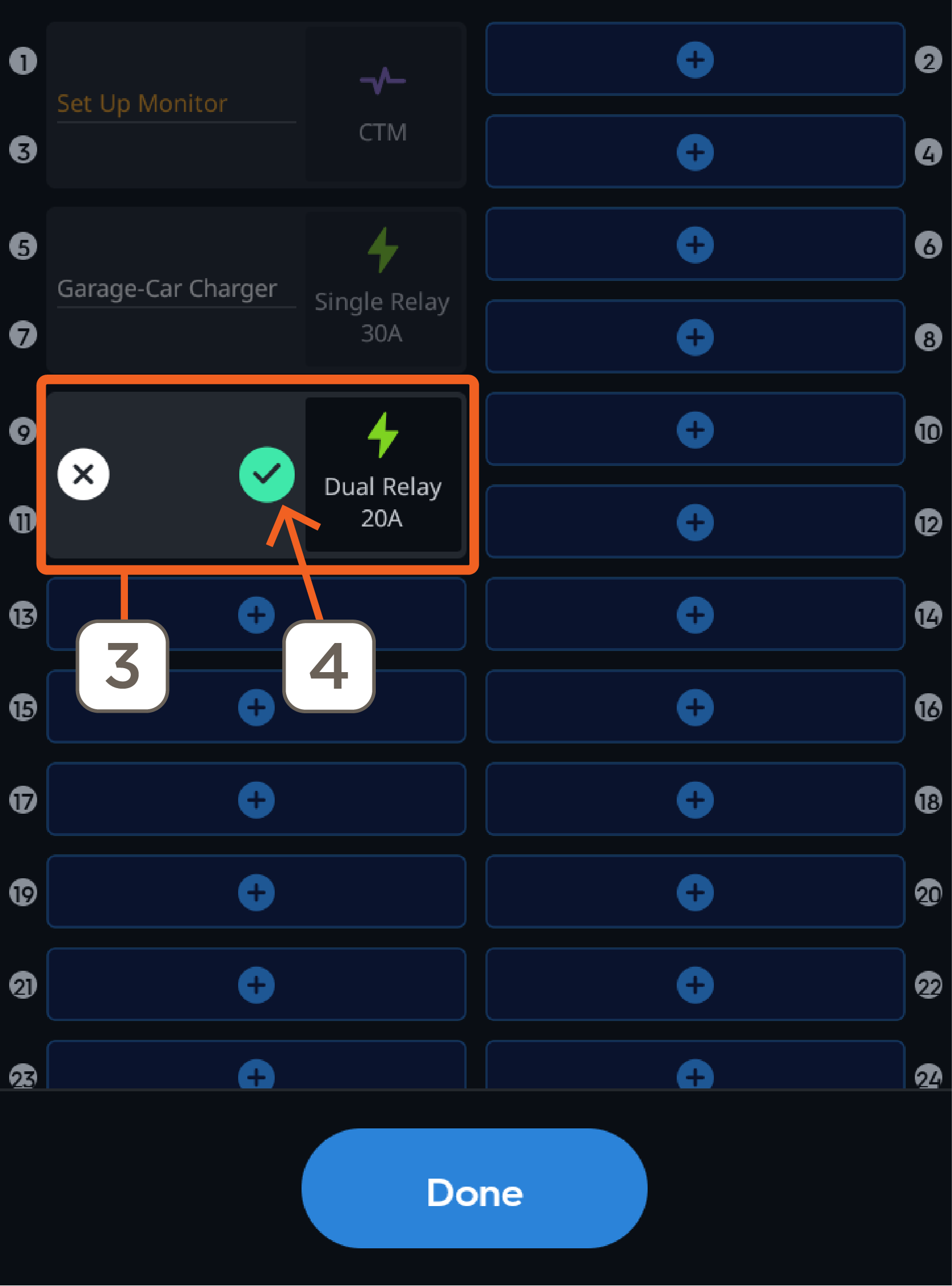
Room and Circuit names are configured on a per-channel basis. A Channel Circuit is the relay within Power Module that controls the circuit it is wired to. Dual relay Power Modules have Channel A Circuit and Channel B Circuit, while single relay modules have only Channel A Circuit. The image below shows the process of configuring the Power Module Space Group, Space Numbers, and the optional Channel Room Name and Channel Circuit Name of a dual relay Power Module:
3. Create a Home
After the Director and Modules are physically installed, follow the steps in the next sections within the SP&L app. The app will guide the user along the way when creating a Home and setting up a new Power System for the first time. For existing systems, skip down to the relevant section as needed.
A Home is a representation of the Savant Power System in the Power & Light app.
- Sign up for a new account or use an existing account to log in.
- Tap System Configuration and allow location permissions.
- Tap Add New Home (plus icon).
- Enter a name for the home (e.g., “Emerson Home”) and tap Next.
- A photo represents the home within the SP&L and Savant app. Tap Set Home Image to select an image, or tap Next to skip this step and a default image will be applied.
Note: The Home image can be set up at a later time.
4. Select System Type
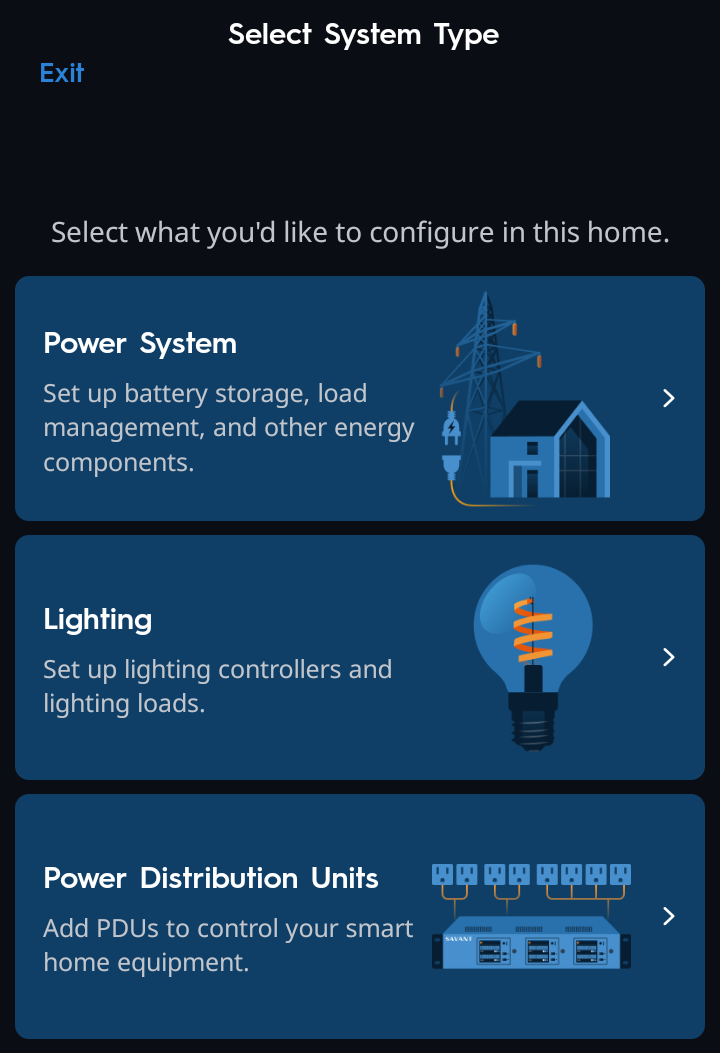
There are three system types available: Power System, Lighting, and Power Distribution Units. To learn how to set up a Power Distribution Unit, refer to the Savant Power Distribution Unit (PDU) Deployment Guide on the Savant Customer Community. For a Lighting only system select Lighting.
This guide goes over setting up a Power System.
Set Up a Power System Home
Follow the steps below to add a Director and configure the Home.
- Select Power System.
- The app will automatically scan for a Director on the network. Once discovered, select the Director.
- For panels using Savant Power Modules, select Yes...
For panels that are energy monitoring only (not using Savant Power Modules), select No...
NOTE: This guide assumes that Savant Power Modules are installed in the panel.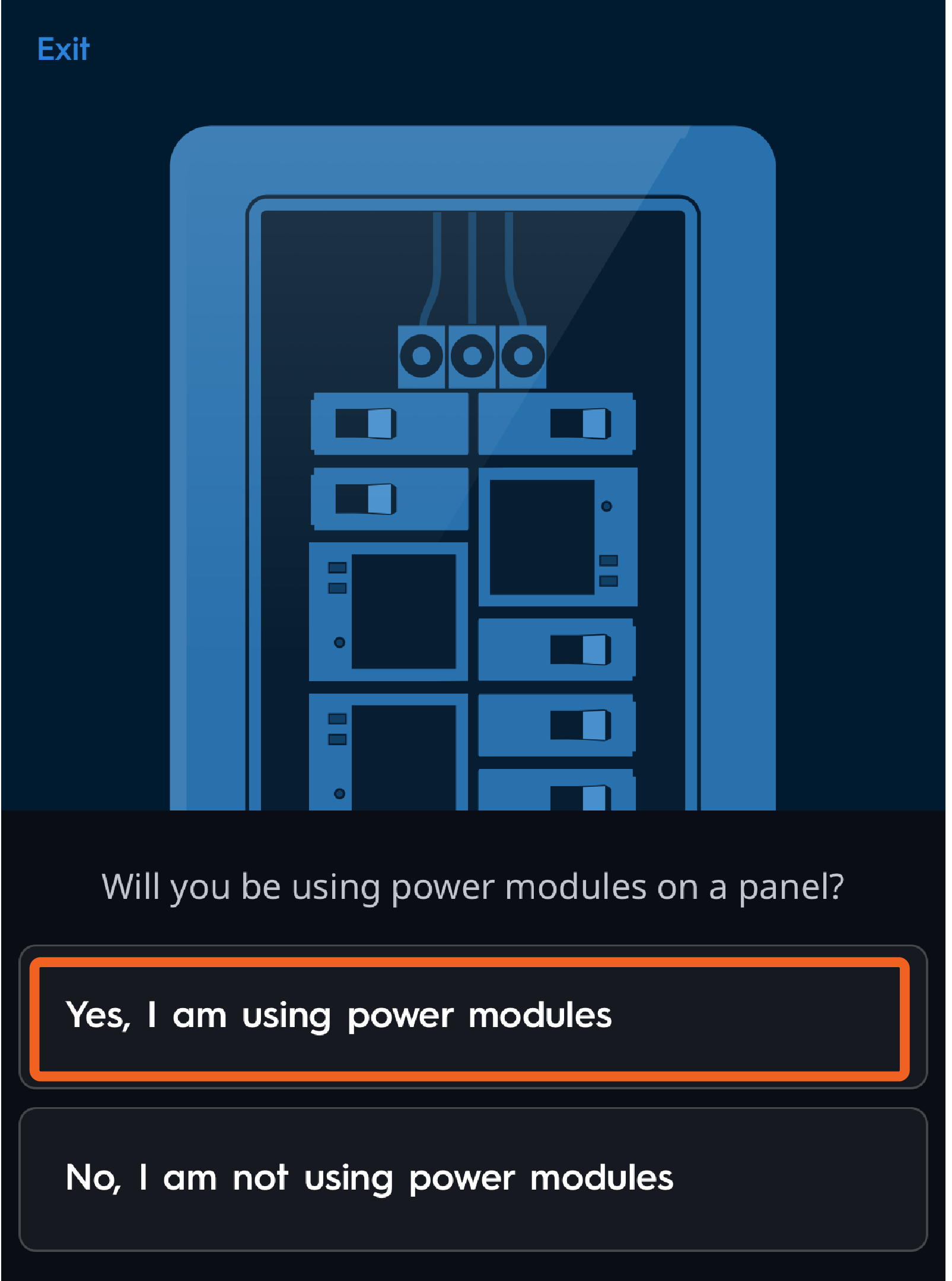
- Select Yes, I am using power modules, Enter the Home Size (ft²), then tap 'Next'.
NOTE: If the app prompts the user to update the Host version, Savant recommends updating the Host before continuing. Refer to the Software and Device Firmware Update Procedures for more details on updating the Director.
5. Panel Configuration
System configuration for each Home within the SP&L app is represented by virtual breaker panels, each containing a Power Module placed in the space matching the physical panel layout on site. Modules are then paired with the virtual panel via the app, and the configuration is synced to the Power Director. The following sections describe how to add Breaker Panels and Power Modules to the Director's configuration.
Add Breaker Panel
Follow the app's guided instructions to add a breaker panel. This process can be repeated for each additional breaker panel as needed.
- Select Add Panel to create the Main Distribution Panel.
- Select panel type (Split or Three Phase).
- Set the amperage of the panel's Main Breaker.
- The app will display basic panel settings, including Name, Spaces, Number of Columns, and Manufacturer. Tap Next.
- When asked, "Is the panel controlled?..." Select the Director or PBC that will be controlling the panel. The Director is selected by default.
Optional: If Panel Bridge Controllers (PB-P2000 only) were not provisioned to the network, the Installer can select Add Controllers to scan for PBCs and initiate the Wi-Fi provisioning process.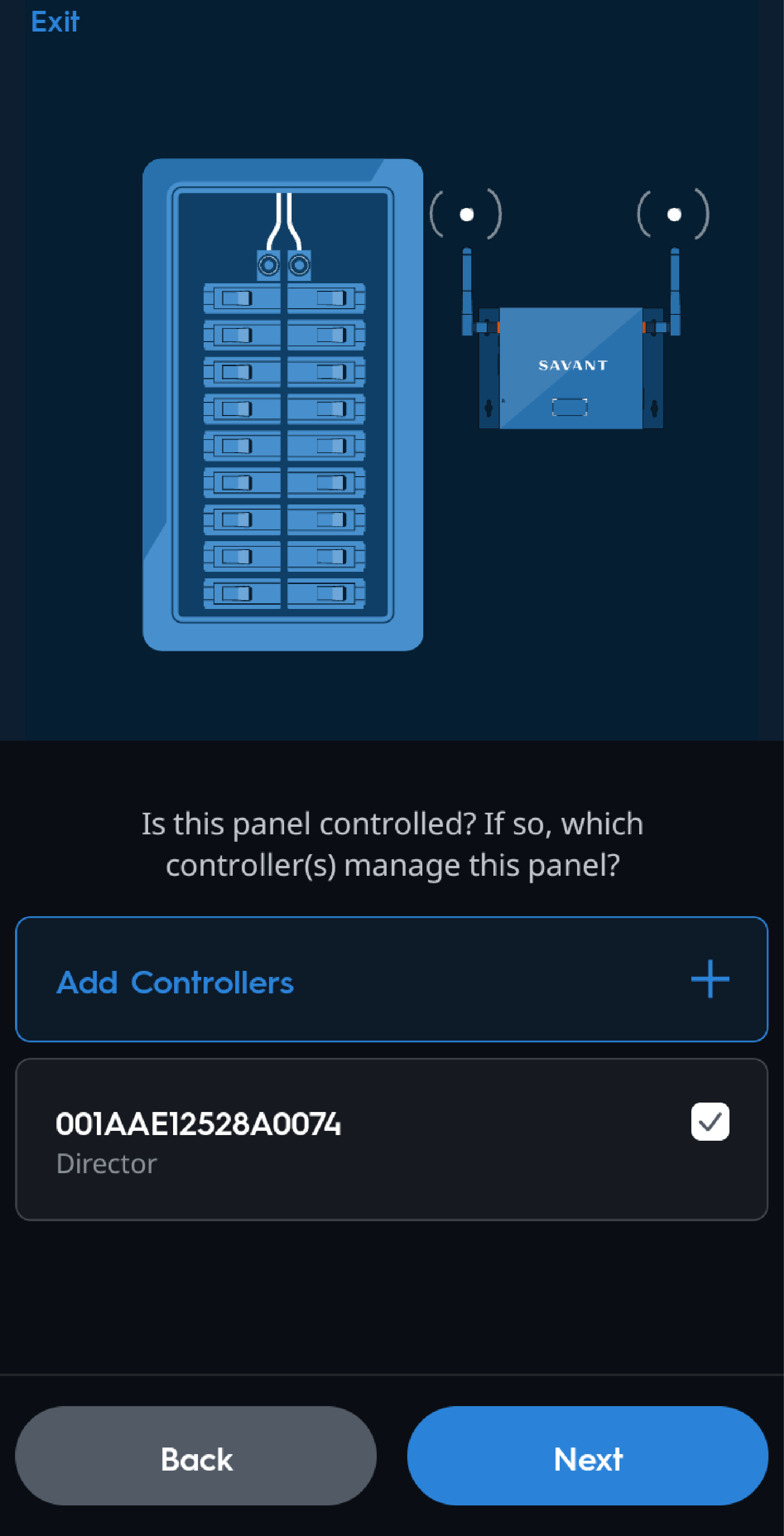
Tap Next to proceed to the next section of adding Power Modules to the panel.
Add Modules to the Panel - Panel Pairing Wizard
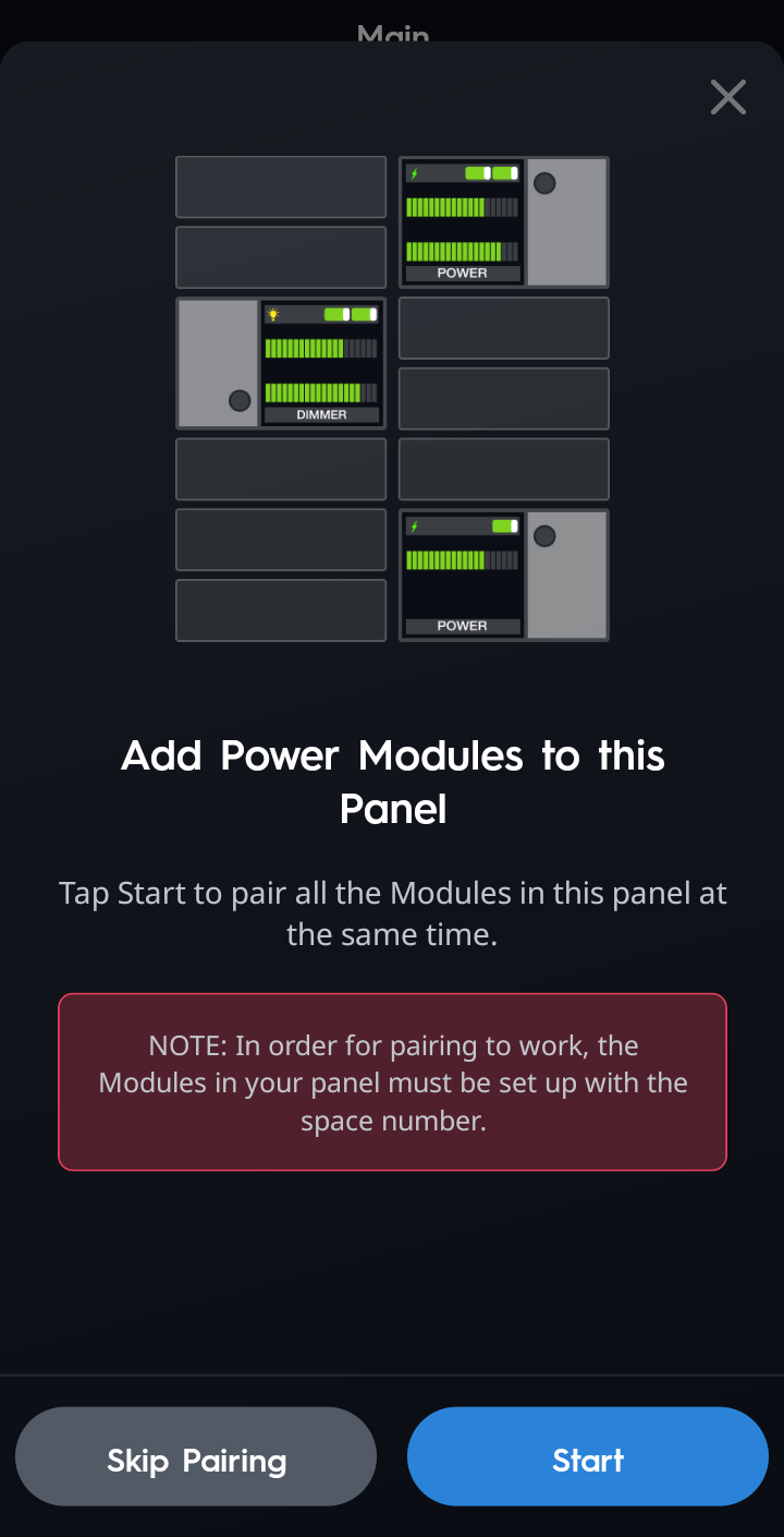
After creating a panel, the Panel Pairing Wizard starts automatically. Follow these steps to pair all Power Modules in the panel at the same time.
- When the following screen appears, read and ensure that the power modules are programmed with a specific space number via the module's on-screen menu, then tap Start.
- Set Modules to Pair Mode. Press and hold the Pair button on each module in this panel until a gear icon
 appears on the module's screen (about 2 seconds). Once all modules in this panel are in Pairing Mode, tap Next.
 - Once the success screen appears, confirm that the module's screen now shows the BT paired icon
 , and tap Next.
HELPFUL TIP: If a module doesn't have the BT icon, or the user forgot to put a module into pairing mode, tap Scan Again to pair the remaining module/s.
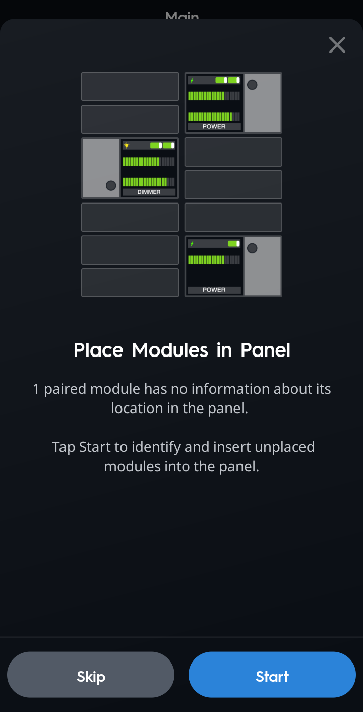
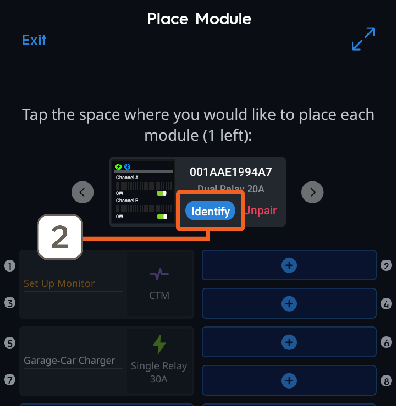
Error Handling - Unmapped Modules
If the following message appears, one of the paired modules was not programmed to a space as instructed in the section above.
 |
|
 |
|
 |
|
Name Circuits
Tap Start to assign or edit the Power Module's room and circuit names. If names have already been assigned tap Skip.
- Select Room Name (example Kitchen), tap Next.
- Select the Circuit Name. Note that the default circuit names start with the Room name previously selected, followed by the Circuit name. Example: Kitchen-Lt&Out
Add Circuit Breakers to the Panel
Use the Quick Add Breakers wizard to place all standard breakers into the panel overview. This information is used when calculating the Smart Budget used in Energy Scenes.
- Select Start and follow the app's guided instructions.
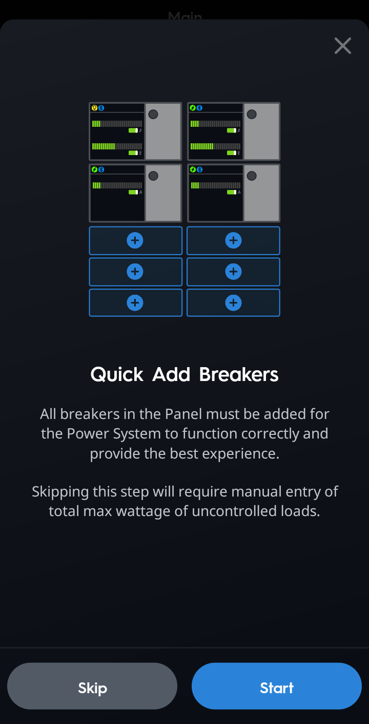
HELPFUL NOTES:- If different breaker types are needed, tap Breaker Type to select a different type and size, then tap the matching breaker space to add the breaker.
- To delete a breaker, tap the X next to the circuit.
- Once all breakers are added, tap DONE.
- On the next screen answer Yes or No if the Home has a Sub Panel.
- Yes will relaunch the Add a Panel wizard.
- No will continue with setting up the Panel.
 IMPORTANT NOTE: All panels should be added, and filled with the correct breakers and modules before continuing with the remaining setup
- This guide assumes no sub-panels are needed. Tap NEXT to proceed to the Link Modules to Breakers section below.
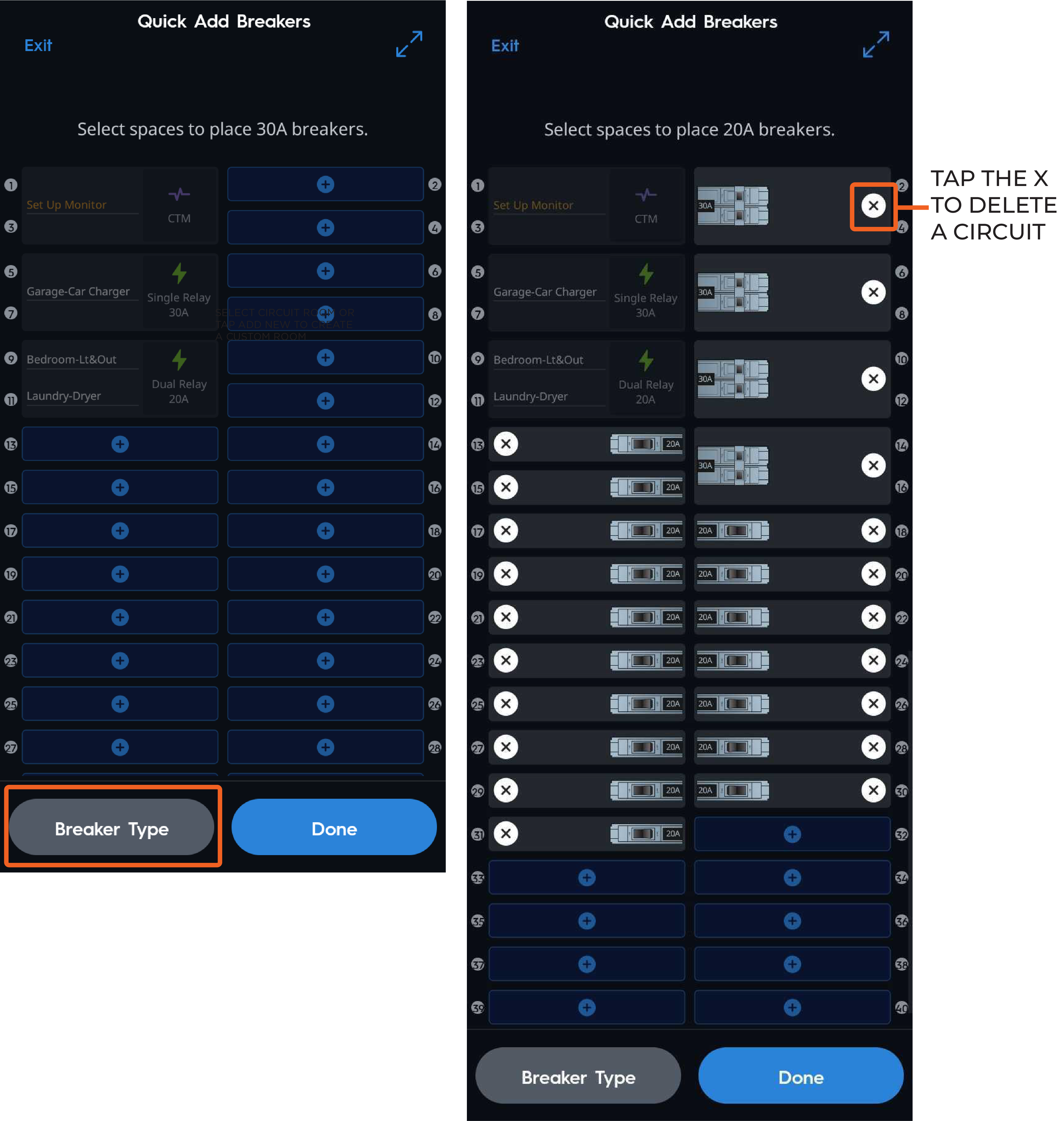
Link Modules to Breakers
Linking Power Modules to Breakers allows the system to identify if circuits are controlled or non controlled and uses this information to create a Smart Budget for Energy Management. Savant recommends NOT skipping this process, as it is required, but can be completed later if needed.
- Tap Start.
- Tap a Power Module and then tap the breaker it controls.
- Once a Module and a Breaker are both selected, the Link button will appear. Tap Link.
- Repeat steps 2 and 3 for the remaining modules until all modules are linked. For dual-channel modules, each channel (A and B) must be linked to separate circuits.
NOTE: Circuits that are linked will be highlighted in green. The breaker will adopt the name of the Power Module and both circuits will show the panel space number that it is linked to. - Once all module channels have been linked to the respective breakers, tap Finish.
Example of all Modules linked to circuits.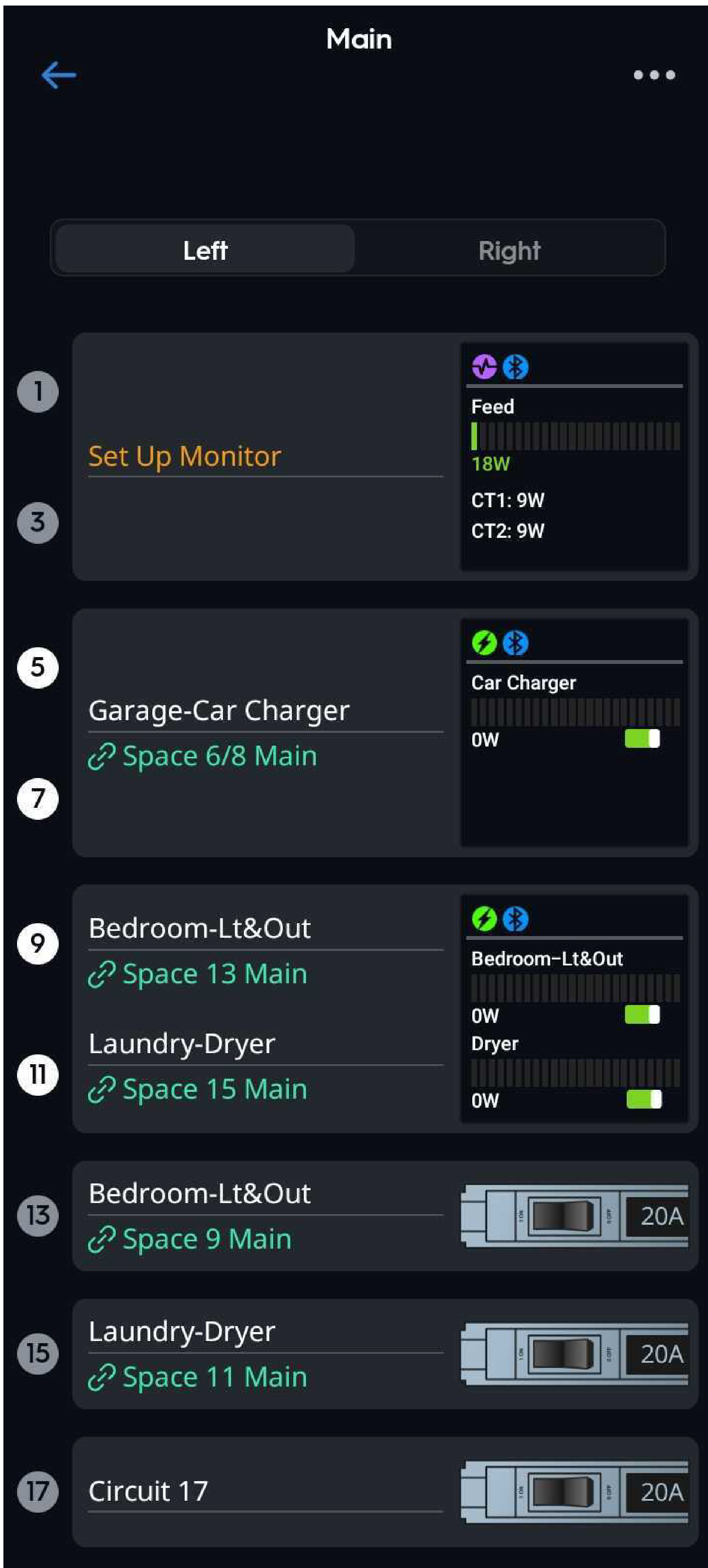
Error Handling - Unlinked Modules
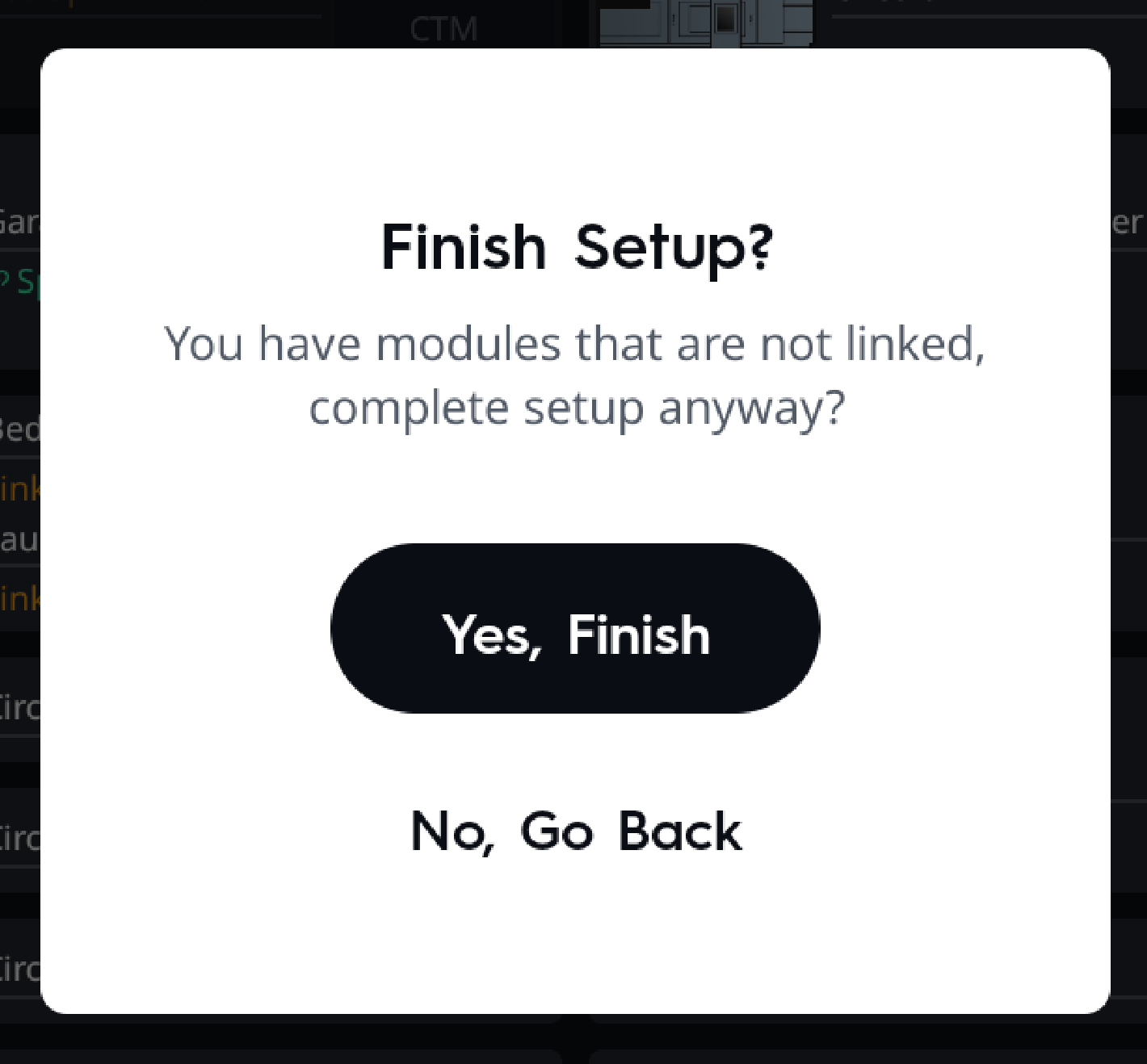
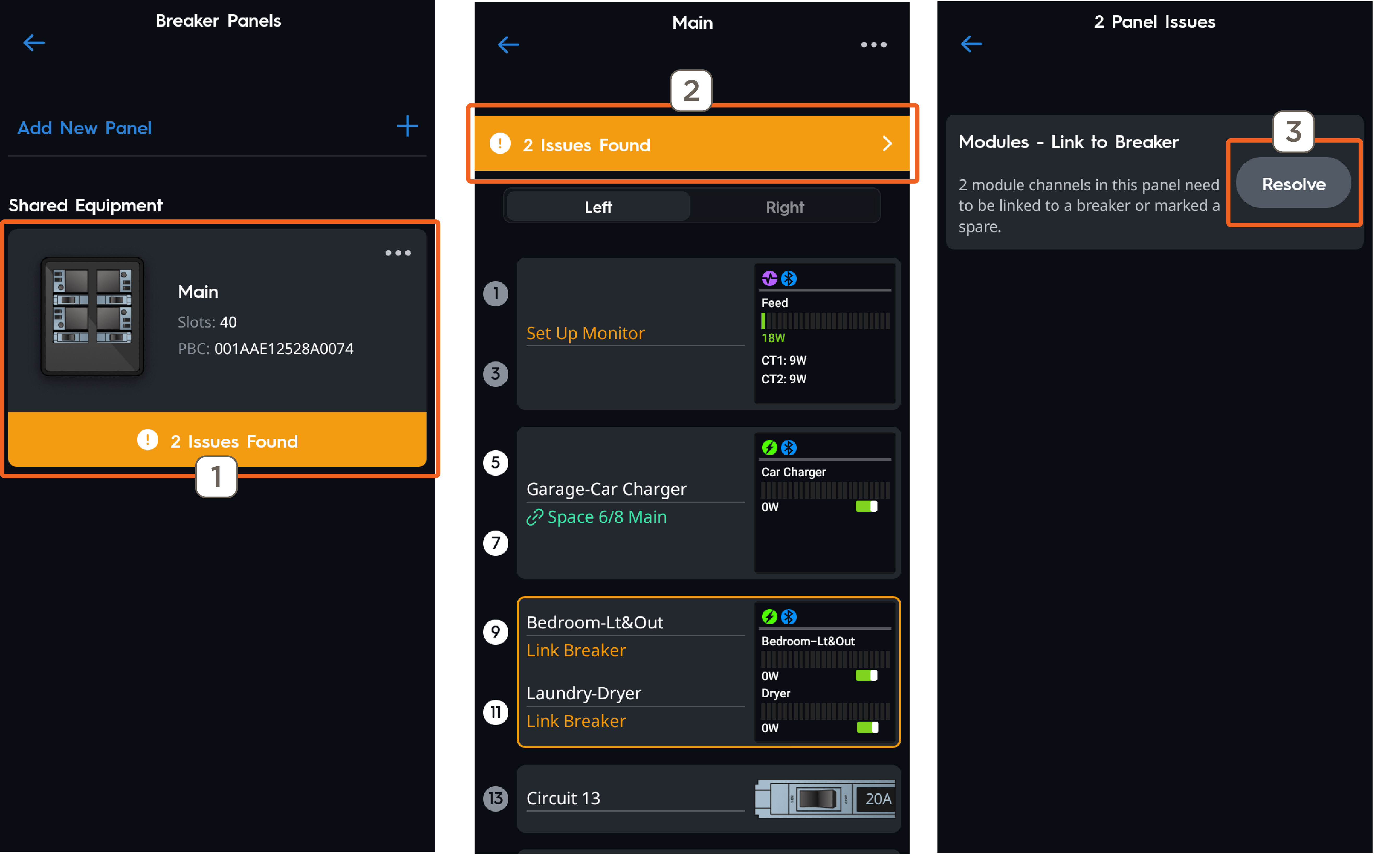
If the following message appears after tapping Finish, Savant recommends going back and complete linking any missed modules before proceeding. If Yes, Finish is selected, the Panel Overview will report there are issues that need to be resolved, shown in the following example. To resolve these issues, follow the steps below.
- Tap the Panel from the Breaker Panels screen.
- Tap the disclosure triangle on the orange banner next to # Issues Found.
- Tap Resolve.
- The Link Modules to Breakers wizard will relaunch. Complete linking on any modules that were missed, then tap Finish.
Set Up Current Track Modules (CTM)
NOTES:
- Skip this section if the panel does not contain any CTMs
- Refer to the Current Track Module Overview below for more information on reversing the polarity if needed.
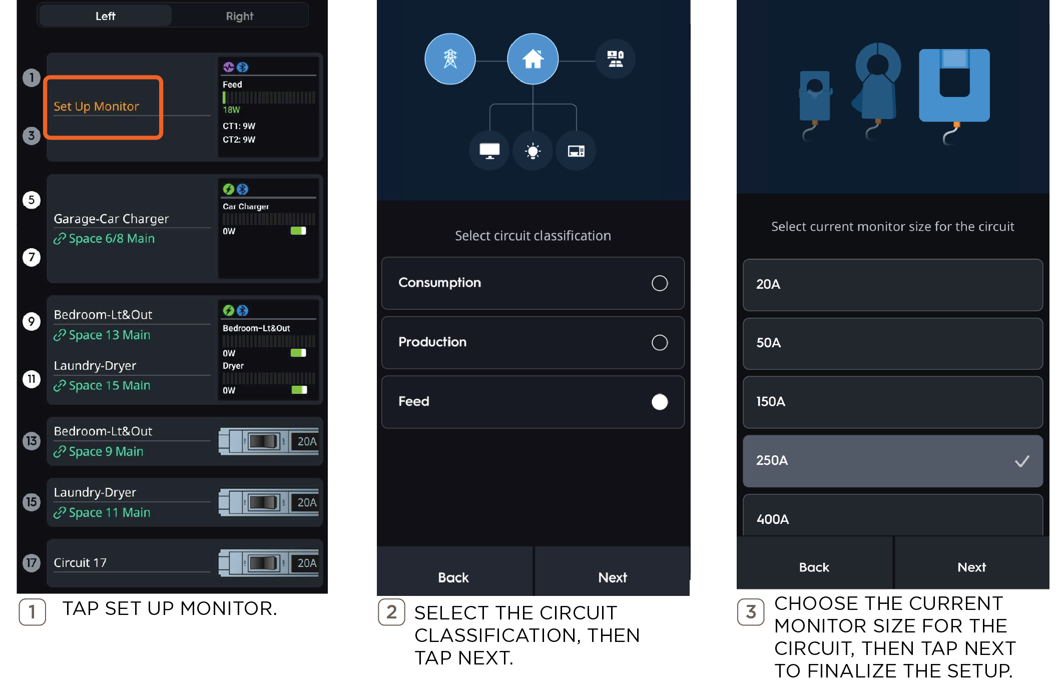
Follow the steps below to set up Current Track Modules.
Set Up Uncontrolled Breakers
Naming uncontrolled circuits will help to identify them later in the setup when configuring Energy Management.
- Tap the default name of an uncontrolled breaker (Circuit XX)
- Tap Configure Breaker
- Choose a circuit name from the list or enter a custom name.
- Select whether the circuit is Dedicated or non-Dedicated.
- An estimated Max Wattage is assigned based on information collected during setup. Max Wattage can be edited if the calculated value is not correct.
- Repeat steps 1 - 5 for the remaining uncontrolled breakers.
IMPORTANT NOTE!: These details will be used to more accurately calculate the energy budget for use in Energy Scenes.
Panel Setup Complete—Next Steps
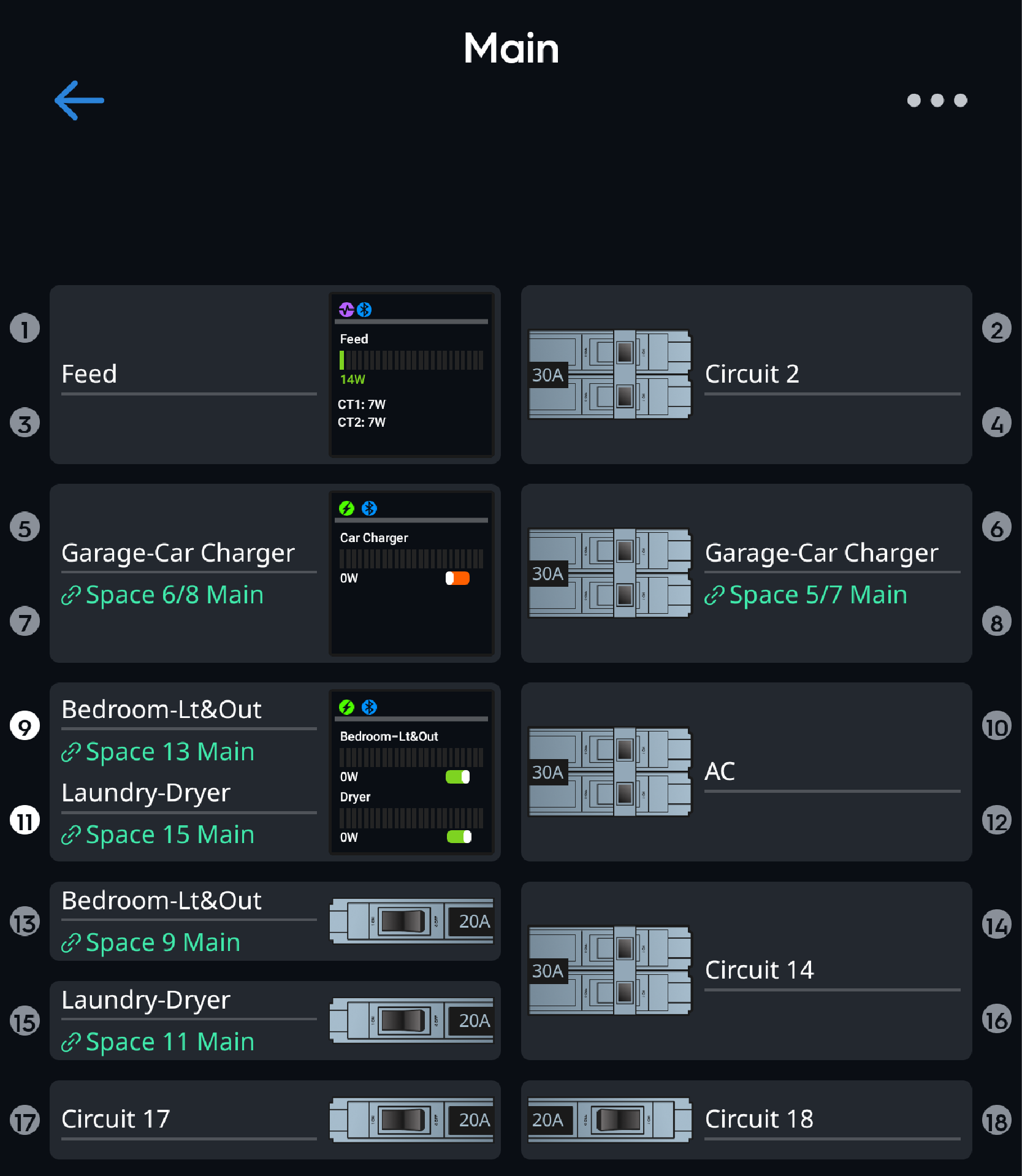
Once all Power Modules are linked and uncontrolled circuit breakers have been added and configured, the guided panel setup process in the app concludes, returning to the Main Panel View, shown below. For additional details about the main Breaker Panel view, the Power Modules, and Circuit Breaker, refer to the Panel Overview and Power Modules Overview sections.
![]() IMPORTANT NOTES!:
IMPORTANT NOTES!:
Read the following to continue making configuration changes in the app.
- Navigate back to the Main Dashboard (Breaker Panels, Power Sources, Energy Management, and Add/Remove Devices).
- If the system includes a GE Smart Water Heater, Thermostat, Savant EV Charger, or Energy Monitor), refer to the links listed at the beginning of this guide.
- If the system includes a battery or generator continue to the Creating a Power Source section for setup instructions.
- Once all components in the system have been added to the configuration, proceed to Energy Management to set up Energy Scenes.
- To complete setup and upload the configuration to the Director, tap the orange Sync button located on the bottom banner of the Home Dashboard.
Dashboard - Power System
The Home Dashboard displays all available setup options. Depending on individual system components and design, some options may not be used. The table below provides information about each tile and its function.
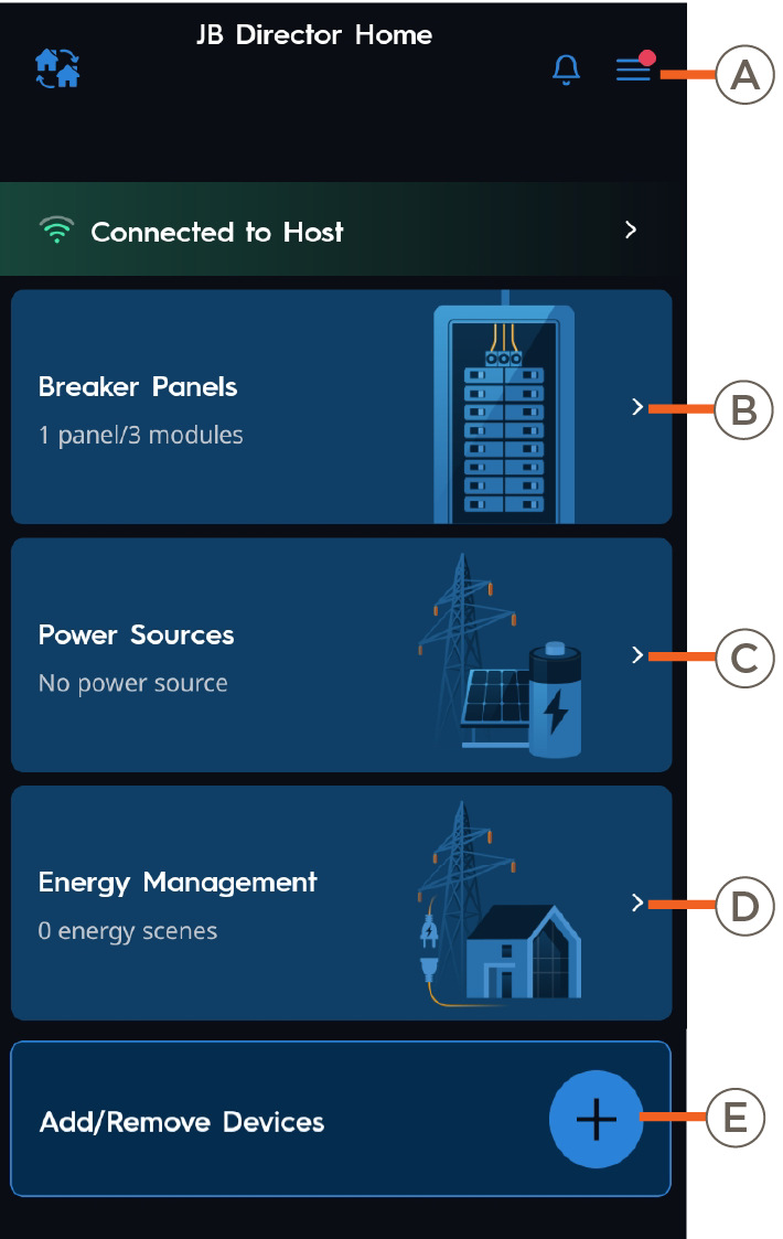 | A | Menu |
Tap to open the Menu screen, to reveal the following options:
|
| B | Breaker Panels |
Tap to view and edit Breaker Panels. Quantity of Breaker Panels configured. Quantity of Power Modules configured. | |
| C | Power Sources |
Tap to view and configure a Power Source. Type of Power Source (Battery or Generator) configured. | |
| D | Energy Management |
Tap to view and edit Energy Scenes, edit circuit settings, and energy scenes. Quantity of Energy Scenes configured. | |
| E | Add / Remove Devices |
Tap to add or remove the following devices, then tap SAVE.
|
6. Additional Power System Devices - Optional
For additional Power System options, (GE Smart Water Heater, Thermostat, Savant EV Charger, or Energy Monitor) It is recommended that these devices be added before proceeding further in this guide. Refer to the links listed at the beginning of this guide. Once the device has been completly set up, return to this guide and continue with the section below.
7. Adding a Power Source
This section of the guide describes the process for adding a Power Source (generator or battery storage system) to the configuration. Complete this section if the Savant Power System has been designed to include a Power Source.
NOTE: Creating a Power Source is required for Off Grid Energy Scenes.
- Tap Power Sources from the main Dashboard
- Tap the blue + button to add a Generator or Battery Energy Storage System.
- Select a power source profile from the list of supported system types.
- Configure each setting in the power source profile.
Refer to the Power Source Settings article for more detailed descriptions of each profile. - Select the breaker panel that the power source will back up, then Next.
TIP: If only one panel was configured, then there will only be one option available.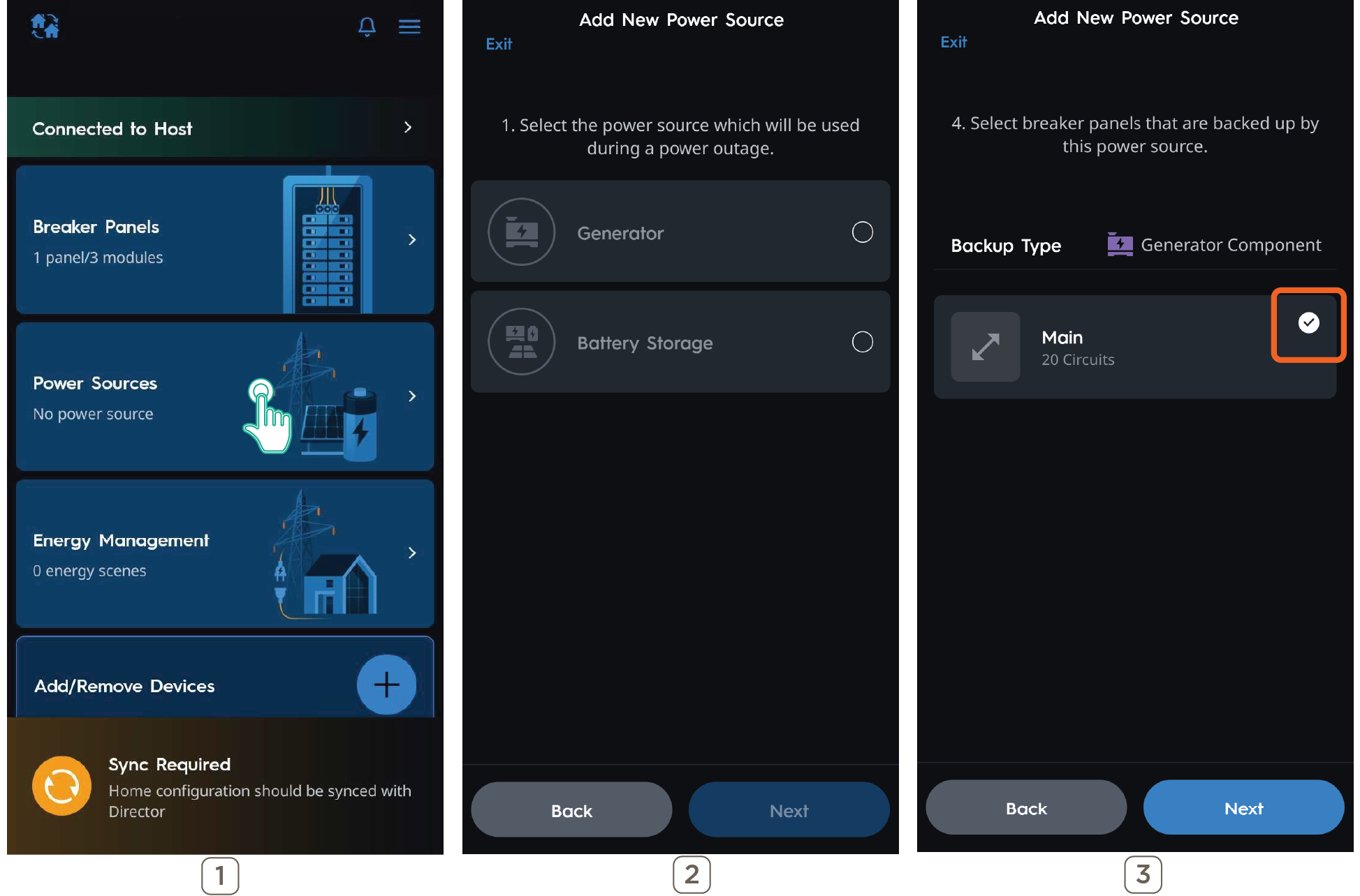
- Back out to the main System Dashboard.
NOTE: The Power Sources tile now has the name of the power source that was configured in the previous steps.
8. Energy Management
Energy Management contains settings that determine how the system will behave during an Off Grid event and where Energy Scenes are created.
This section is optional if the system does not contain a backup power source.
Energy Scene Priority List (Off Grid Scenes Only)
- In the event of a power outage, the Essentials scene will be activated and power critical circuits, while shedding non-critical circuits.
- If the battery state of charge has reached a level that matches a battery level in an Off Grid Scene condition when the grid goes down, that particular Off Grid Scene will activate.
- If the battery reaches a state of charge that matches a battery level in a Scene condition while the grid is down, that Off Grid Scene will activate.
![]() IMPORTANT NOTES!:
IMPORTANT NOTES!:
- Once a default scene is created for the first time, the app requires a one time sync to the Director before allowing any additional customized scenes to be created. Afterwards, creating or modifying customized scenes will not require the app to sync to the Director.
- If the system has a power source (generator or battery) then a default Off Grid scene is required before syncing to the Director.
- Default scenes cannot be deleted once created nor have its' automation conditions changed.
General Settings
Home Size: Used to calculate default Circuit Max Wattages
Circuit Settings: Configure circuit max wattages and identify dedicated circuits
Restore Circuits to Previous State: Circuits turned off during a grid outage event will turn back on when the grid becomes available
Circuit Settings
This menu should be reviewed before any Energy Scenes are created. The following describes the function of each menu within Circuit Settings.
Dedicated Tab:
Check a circuit to mark it as a Dedicated Circuit.
- Dedicated Circuits power a single appliance or load such as a Microwave or Heat Pump.
- The Max Wattage of a Dedicated Circuit will default to 80% of the circuit's capacity. For example, a 30A circuit Max Wattage will default to 5,760 watts.
Uncheck a circuit to mark it as Non-Dedicated.
- Non-Dedicated Circuits typically power lights, outlets, or smaller loads.
- The Max Wattage of Non-Dedicated circuits will default to a value based on information gathered during setup.
Max Wattage Tab
This menu shows information about the Max Wattage assigned to controlled and uncontrolled circuits. It is important that these values are correct as it will impact how many circuits can be powered on when creating an Energy Scene.
Manual Entry: This setting is toggled off by default. These settings are automatically populated based upon the Breaker Panels created in Section 4 – Panel Configuration. Enabling Manual Entry allows custom values to be entered in each field.
Usage Percentage: Moving the slider will decrease or increase the assigned Max Wattage of all non-dedicated circuits. It will not affect any circuits with a Max Wattage that has been modified from its original assigned value.
Circuit Max Wattages: Every circuit in the system will be listed with its assigned Max Wattage. Max Wattage is defined as the highest possible value, in watts, that circuit can be expected to consume.
8.1 Energy Scenes
Energy Scenes are used to control which circuits need to be on or off during a Grid Outage to ensure the backup power source is not overloaded. On Grid Scenes can also be created that turn off large loads during times when energy rates are high or simply conserve energy when loads are not in use.
Creating an Off Grid Scene
After adding a power source, follow these steps to create an Off Grid Scene. A minimum of (1) Off Grid Scene is required when the backup power source cannot support the entire load of the home. If the system does not require a Smart Budget, a Default Off Grid Scene is not required.
- From the Main Dashboard view, select Energy Management, then + in the top right.
- Select Next.
- If a Default Off Grid Scene is required this step will automatically start, otherwise the following Off Grid Scene types can be chosen:
- Battery Drops to Level – Activates when the battery drops to the set level while the grid is down.
- Grid Goes Down – Activates on a Grid Outage Event.
- Time Schedule – Activates at a specific time while the grid is down.
- Tap to Run – Is only activated when the scene is selected by the user.
- Select which circuits are powered on when the scene is activated.
- Circuits not checked will be powered off.
- If the system utilizes Smart Budget, it will adjust based on how many circuits are selected. The smart budget is disabled if a user has disabled the budget during power source creation, the budget will still appear even if a user has an exceedingly large power source.
- Tap Next, then Save. The Off Grid scene is created.
Creating an On Grid Scene
On Grid Scenes are optional and can be created by the homeowner in the Savant app.
- From the Main dashboard view, select Energy Management. The app will ask the user if all devices have been set up.
- With all devices already set up, select Yes.
- Tap the + button to create a new Energy Scene.
- Select On Grid for Grid State.
NOTE: This step is automatically skipped when the system does not include a backup power source. - Select how the scene is activated:
- Time Schedule – Activates a specific time while the grid is available.
- Tap to Run – Is only activated when manually selected by the user.
- Select which circuits are powered on when the Scene is activated.
NOTE: Circuits not checked will be powered off. - Name the Scene, then Save.
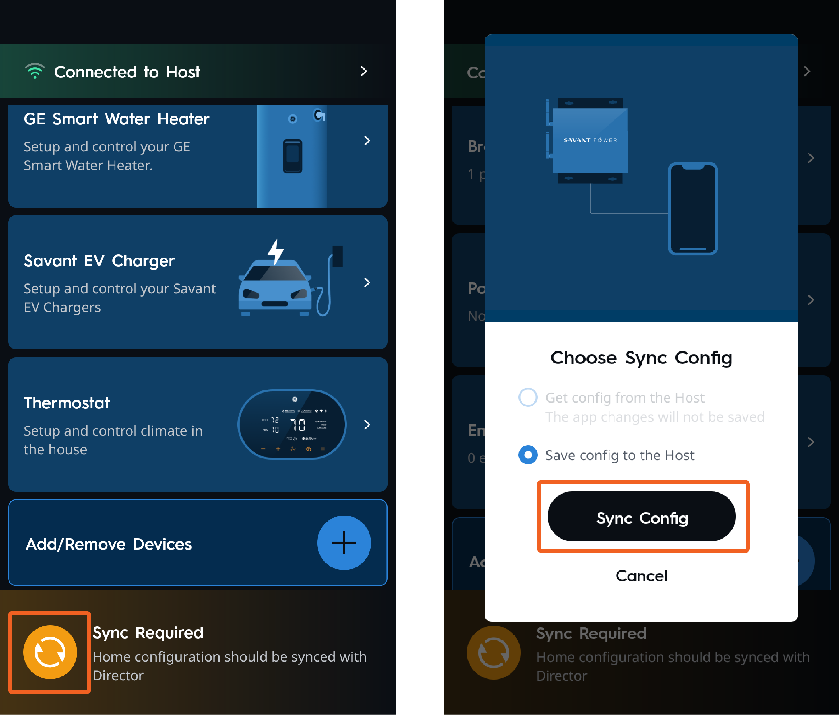
9. Get or Sync Config
Once all devices and scenes are created, sync the Config by tapping the sync button. All devices and their settings are stored as a Config file on the mobile device. A config file needs to be saved to the Host before the following options become available.
- Get Config: Downloads the config from the Director to the mobile device for editing and overrides the locally saved config on the mobile device.
- Save Config to the Host: Config is uploaded from the mobile device to the Director to save any changes made.
- Cancel: Backs out of the Sync Menu. When Savant Power and Light connects to a Director, Skip allows navigating directly into the Configuration if there is a configuration locally saved on the mobile device.
- Continue Editing: Only shows up if the user was previously editing locally, but never synced, and had closed the app.
10. Confirm System Functionality
Once the configuration is synced to the Director, the Savant Power & Light app configuration is complete. However, it is important to test the system to ensure correct functionality.
- Check that all circuits are named correctly on the Power Module display
- Check that all circuits and modules are placed correctly
- Confirm that circuit power readings appear correctly on Power Module display
- Ensure that all circuits can be powered on and off
- Check that all loads report energy readings properly
- Check that total consumption, battery, and grid power are reported properly
- Take the system off the grid and check that the appropriate off grid scene triggers
- Test all configured off-grid scenes — check that the load states are set accordingly
- Bring the system back onto the grid and check that all loads are restored
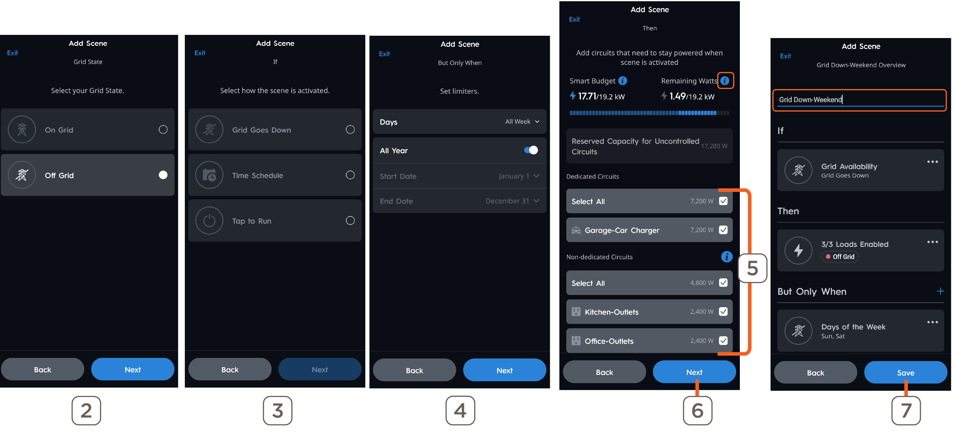
11. Creating Custom Scenes - Optional
- From the Dashboard view, select Energy Management > + > Next.
The app will guide the user step by step to configure the three automation parts of a custom scene: IF, THEN, and BUT ONLY WHEN. - Select Grid State.
- On Grid Scenes will only trigger when the Grid is available.
- Off Grid Scenes will only trigger when the Grid is down.
- Select an IF option, then Next.
NOTE: Off Grid has four available IF conditions (Grid Goes Down, Time Schedule, Tap to Run, and If Battery Drops to Level), while On Grid has Time Schedule and Tap to Run. - Grid Goes Down (ONLY) Set the limiters (days of the week, and whether it's all year or certain start/end dates.
- Verify if the correct dedicated and non-dedicated circuits are selected; if not, select or deselect the correct circuits.
HELPFUL TIP: Tapping on the blue information icons provides additional information. - Tap Next.
- Tap to edit the Scene Name, then Save.
Breaker Panel Settings
The breaker panel settings can be accessed by navigating to Breaker Panels > ... > Settings. Refer to the manufacturer's documentation to confirm the following settings are correct before uploading the configuration to the Director.
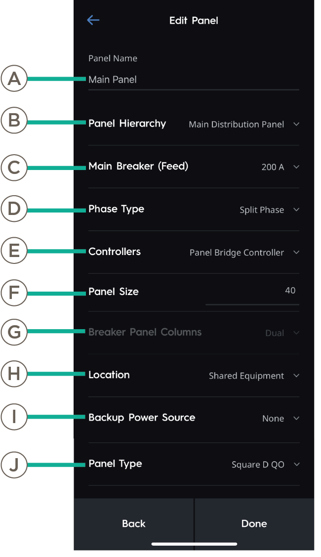 | Setting | Definition | |
| A | Panel Name | Name of the breaker panel as it will appear in the Power & Lighting app. | |
| B | Panel Hierarchy | Main Distribution Panel: Panel will control distribution of power throughout the Savant Home. Sub Panel: Panel is powered by the main distribution panel. | |
| C | Main Breaker (Feed) | Current output from the main feed into this panel. | |
| D | Phase Type | Split phase or three phase | |
| E | Controllers | Which controller is controlling modules within the panel. | |
| F | Panel Size | Quantity of spaces in the breaker panel. | |
| G | Panel Breaker Columns | Quantity of columns in the breaker panel. | |
| H | Location | Room within the Power & Light App the breaker panel is located. | |
| I | Backup Power Source | Which Power Source is backing up the panel. | |
| J | Panel Type | Make and Model of the breaker panel. |
Breaker Panel Overview
The Panel Overview is a visual representation of the Breaker Panel. Paired Power Modules are shown in their assigned Space and display their current status.
- Tap a Power Module to edit its settings
- Tap an empty panel space to add Power Modules or Breakers.
- The quick add breakers, breaker linking, and pairing wizards can be relaunced at any time by selecting the ellipsis(...) in the top right corner of the Breaker Panel screen.
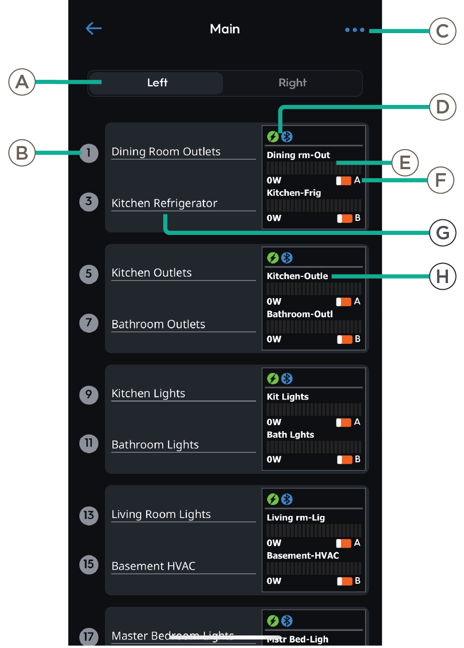 | Panel | ||
| A | Panel Side | Which side of the panel is being displayed. | |
| B | Space Number | Individual space in the panel. Tap to test the associated load. | |
| Module | |||
| C |
Menu | Tap to change zoom setting, start the Quick Pair Modules, Quick Add Breakers, or Link Modules to Breakers guided setups. | |
| D |
Load Type Indicator | Indicates whether the Power Module controls a Lighting or Energy type load. Indicates the Power Module is paired to the Director | |
| E | Power Meter | Live load out of maximum load per channel, in watts. | |
| F | Switch Status | Indicates if the circuit is Powered On or Powered Off. | |
| G | Circuit Name | Name of associated circuit. Tap to assign or re-assign Circuit Name. | |
| H | Display Name | Shorthand name for the circuit. | |
Power Module Overview
Power Module settings can be accessed by tapping the Power Module Screen in the space group. The process is the same regardless of Module type, but settings will differ.
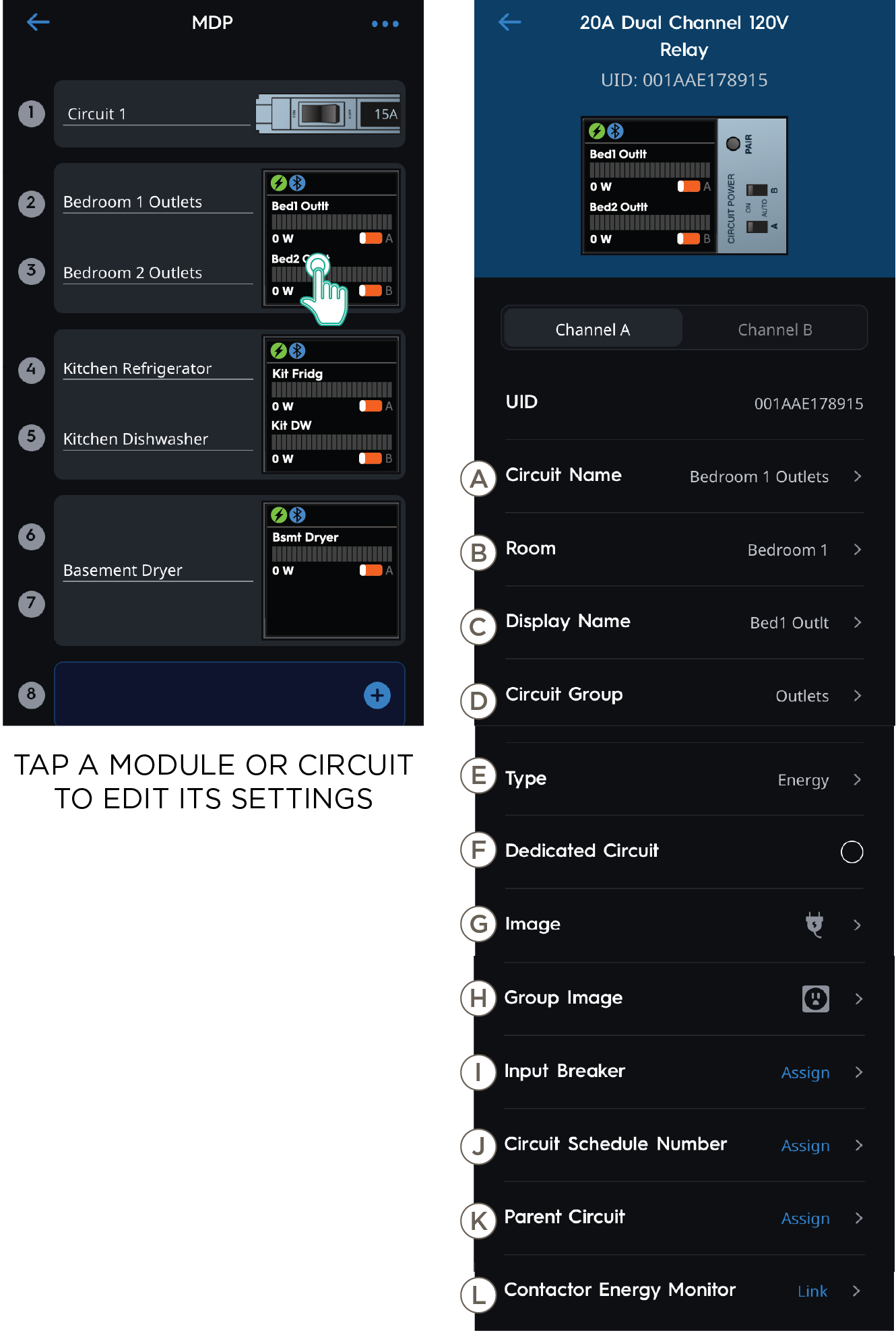 | Setting | Definition | |
| A | Circuit Name | Name of the Channel Circuit. | |
| B | Room | Location in the Home the circuit is associated with. | |
| C | Display Name | Name displayed on the Power Module LCD screen. | |
| D | Circuit Group | Assign a Group to organize circuits by category. | |
| E | Type | Tap to choose Energy or Lighting Module. | |
| F | Dedicated Circuit | Enable to set Channel Circuit as a Dedicated Circuit. | |
| G | Image | Assign an Image to identify the circuit type. | |
| H | Group Image | Image representing the Channel Circuit Group. | |
| I | Input Breaker | The input breaker that is wired to the Power Modules channel. Tap to relink to a different circuit if needed. | |
| J | Circuit Schedule Number | User-defined schedule number for the circuit. | |
| K | Parent Circuit | Tap to assign parent circuit. | |
| L | Contactor Energy Monitor | Tap to assign Contactor Energy Monitor. Refer to the Savant Power & Light App (SP&L) - Adding Smart Energy Monitoring (SEM-2015) for more information. |
Current Track Module Overview
Tap the Current Track Module Screen in the space group, then tap Feed to review and adjust additional settings if needed.
| Setting | Definition | ||
| A | Channel A |
Live voltage, amperage, and wattage reported by the circuit connected to Channel A. Tap the Invert button to reverse the polarities if needed. | |
| B |
Channel B |
Live voltage, amperage, and wattage reported by the circuit connected to Channel B. Tap the Invert button to reverse the polarities if needed. | |
| C | Classification | Whether the Current Track Module is measuring a Feed, Consumption or Production type circuit. | |
| D | Circuit Name | Name of the Circuit. Tap to edit. | |
| E | Production Type (Production Only) | Generator, Battery, or Solar. | |
| F | Current Monitors | Quantity of Current Monitors | |
| G | Channel 1 | CT connected to channel 1 of the Power Module. | |
| H | Channel 2 | CT connected to channel 2 of the Power Module. | |
| I | Room | Location of the circuit monitored by the Current Track Module | |
| J | Image | Image representing the Channel Circuit. | |
| K | Current Monitor Size | Amperage rating for installed current monitor. | |
| L | Group | Group within the Savant Power Home. | |
| M | Group Image | Image representing the Channel Circuit Group. |