Power Module Operation Manual
Document Date: April 2026
Description
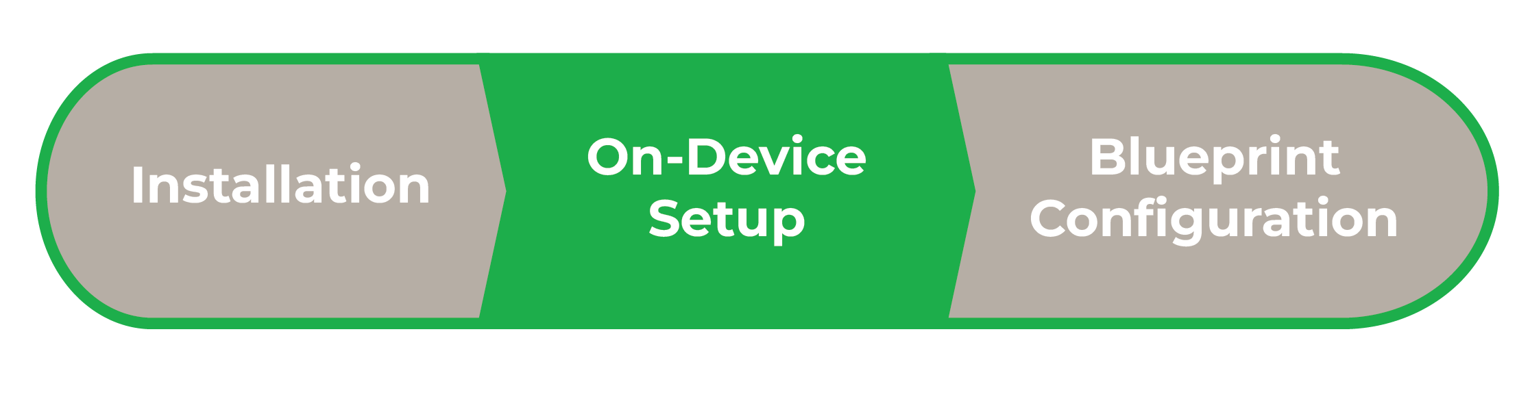
This document describes information related to Power Module functionality and status icon definitions. It assumes Power Modules are installed into a breaker panel and powered on. It is the second stage in integrating Power Modules into a Savant System.
IMPORTANT NOTES!:
- The latest Power Module firmware version is 3.5.27. Modules will automatically update to the latest firmware version if the Host is updated to SavantOS 11.2 or the Director to 11.1.4.
- For information on physical installation of a Power Module, see the relevant Quick Reference Guide on the Savant Knowledgebase.
- After reviewing this document, refer to Savant Power & Light App (SP&L) – Initial Smart Panel Configuration for Savant Power & Light app Configuration or the Lighting & Shades Device Manager Programming Guide - Configure Panels & Panel Bridge Controllers for Blueprint Configuration.
Power Module Overview
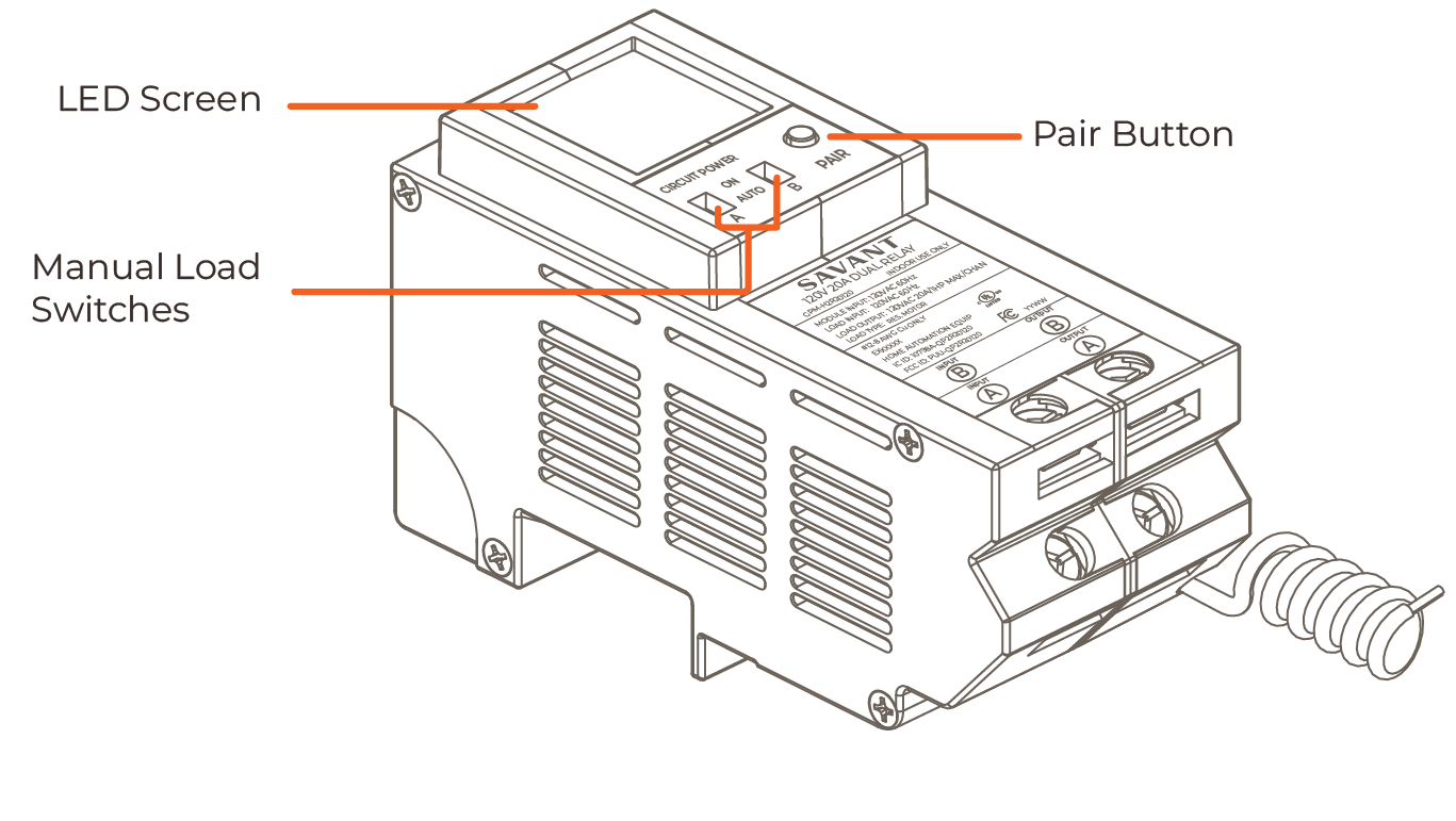
- The Power Module LED screen allows viewing of the real time status of the module. For more information, see Power Module Screen.
- Use the PAIR button to pair the module to a Director or Panel Bridge Controller or navigate screens.
- For information on Pairing Modules to a Director, see Savant Power & Light App - Initial Smart Panel Configuration.
- For information on Pairing Modules to a Panel Bridge Controller, see the Lighting & Shades Device Manager Programming Guide - Panels & Panel Bridge Controllers.
- For information on Pair Button functions, see Pair Button Functions.
- Toggle the Manual Load Switch to switch between AUTO mode or Installer Mode (ON). Installer Mode is only used for when installing the Power Module and should be turned off once installation is complete. The Appendix A: Installer Mode describes the behavior of a Power Module in Installer Mode.
Power Module Screen
The Power Module LED screen is used to quickly understand the state of the Power Module, organized by screen.
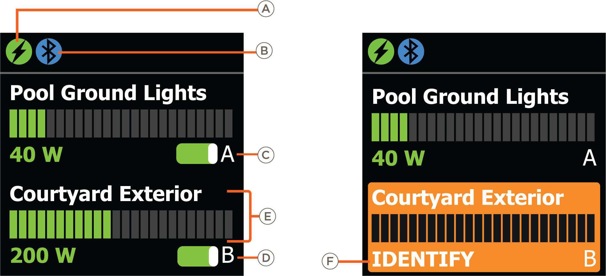
Load Status
| Icon | Description | |
| A | Module Type |  Power Module. Power Module. |
 Current Track Module. Current Track Module. | ||
 Dimmer Module. Dimmer Module. | ||
| B | Module State |  Module is paired. Module is paired. |
 Module is in pairing mode. Module is in pairing mode. | ||
| C | Channel A Circuit Switch | See Circuit Power Switches. |
| D | Channel B Circuit Switch | See Circuit Power Switches. |
| E | Channel Information |
Circuit Name and live consumption (in watts). HELPFUL INFO!: The bar graph scale compares the current load (green) to the maximum load capacity of the Power Module (grey). This ignores the circuit's programmed capacity. Below are the maximum capacities of each type of power module:
|
| F | Identify |
The module is being located using the Identify Device feature. NOTE: Firmware version 3.5.27 and higher will not toggle the connected load ON/OFF and only identify the module using the LED screen. Versions earlier than that will toggle the connected load on/off while in Identify mode. |
Connections
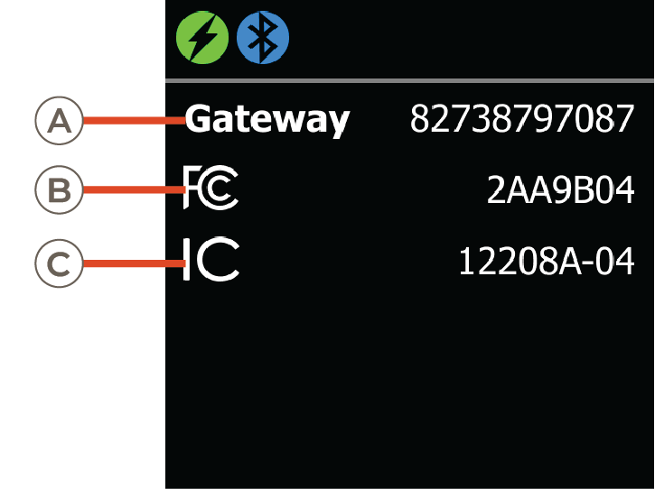
| A | Gateway | The gateway address of the device the Power Module is paired with. |
| B | FCC | The FCC certifications of the Power Module. |
| C | IC | The IC certifications of the Power Module. |
Info
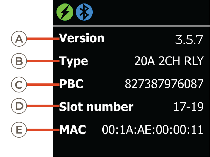
| A | Version | The firmware version the Power Module is running |
| B | Type | The type of Power Module. |
| C | PBC | The UID of the Panel Bridge Controller or Host that is paired to the Power Module. |
| D | Slot Number | Slot number the Power Module is in. |
| E | MAC | MAC address of the Power Module. |
Reset
When the Reset option is selected, this screen displays the UID of the Host, the MAC address of the Module, and prompt the user to Press & Hold for 1 second to confirm Power Module reset.

Circuit Power Switches
The Power Module LED screen and Breaker Panel screen represent the current state of the circuits a Power Module controls as Circuit Switches. The table below lists all possible states and their definitions. Icon definitions are relevant to the type of Home Backup.
| Icon | Description |
 |
|
 |
|
 |
|
 |
|
 |
|
 |
|
 |
|
 | AUTO Mode (Budget Only): See Appendix A: Installer Mode. |
PAIR Button Functions
The PAIR button is located on the front of the Power Module. Pressing the PAIR button, depending on the length of the press, determines its function as listed in the table below:
| Length of Press | Action | Description |
| Press and Release | Cycle | Cycle through screens and actions available in the menu displayed on the Power Module LED screen. |
| Press and Hold (1 second) | Select | Select the option highlighted. |
| Clears the names and assigned slot numbers (when viewing the reset info module screen). | ||
| Press and Hold (3 Seconds) | Pairing | Power Module enters pairing mode. |
| Press and Hold (5 Seconds) | Reboot |
Restarts the Power Module. The display will say reset and count down and connected loads are turned off during the reboot. No names or pairing are lost. |
| Menu Selection | Reset |
Module names and position information is cleared from the module. Pairing is retained (to clear pairing see PB Instructions). Connected loads are not impacted. |
Appendix A: Installer Mode
Turning the Manual Load switch into ON turns the Power Module into Installer mode. Installer mode has the following behavior, depending on the firmware installed:
Older Module Firmware
- If a circuit in the Forced On position is marked Critical (On) in a Scene, the Scene will be allowed to trigger.
- If any circuit in the Forced On position is marked Non-Critical (Off) in a Scene, the Scene will fail to activate.
Firmware 3.5.27 and Higher
- A budgeted system disables the Forced On switch on all Power Modules, so a Scene can never fail due to this condition.
- In a Non-Budgeted system all Power Modules are treated as Critical, even if the Scene has them set to Non-Critical. So Scenes will never fail.