Smart Panel Systems with Generator Only Backup Power Source - Reference Guide
| Document Date: | August 2026 |
Overview
This article guides installers through design and configuration of a Smart Panel system using a generator as the only backup power source.
These steps in this guide describe how to:
- Add and configure a generator as the only power source to a Smart Panel System using the Savant Power & Light app or Blueprint. (If the generator is to be connected to a Power Inverter as part of a Savant Power Storage System, refer to the Savant Power Storage Generator Installation and ATS Integration Guide.)
- Configure Savant Energy Monitor to read the generator and grid feed current. Refer to the Savant Standalone Energy Monitor Quick Reference Guide and the Savant Standalone Energy Monitor Deployment Guide for additional information on how to install and configure.
- Configure Savant Current Track Modules to read the generator and grid feed current. Refer to the relevant Quick Reference Guide for the type of CTM in use and the Panel Bridge Controller Deployment Guide for additional information on how to install and configure.
- Add an Energy Scene to shed loads on grid outage.
Requirements:
- Savant Power Director (HST-DIRECTOR-xx) or Mac Host (SVR-xxxx)
- Generator with automatic transfer switch (ATS)
- GPIO connection from the ATS
- Connected to GPIO input on Director for Director systems
- Connected to any open GPIO input on an SSC controller for Mac Host systems
- Grid feed monitored with Current Track Module (GPM-xxSEM) or Standalone Energy Monitor (SEM-2015) with properly sized pair of CTs
- Generator production monitored with Current Track Module (GPM-xxSEM) or Standalone Energy Monitor (SEM-2015) with properly sized pair of CTs
- Panel Bridge controller is required for Mac Host systems using Current Track Modules
- Additional Savant Power Module (v.3.5 or higher) are required for circuit management or load shedding upon grid outage
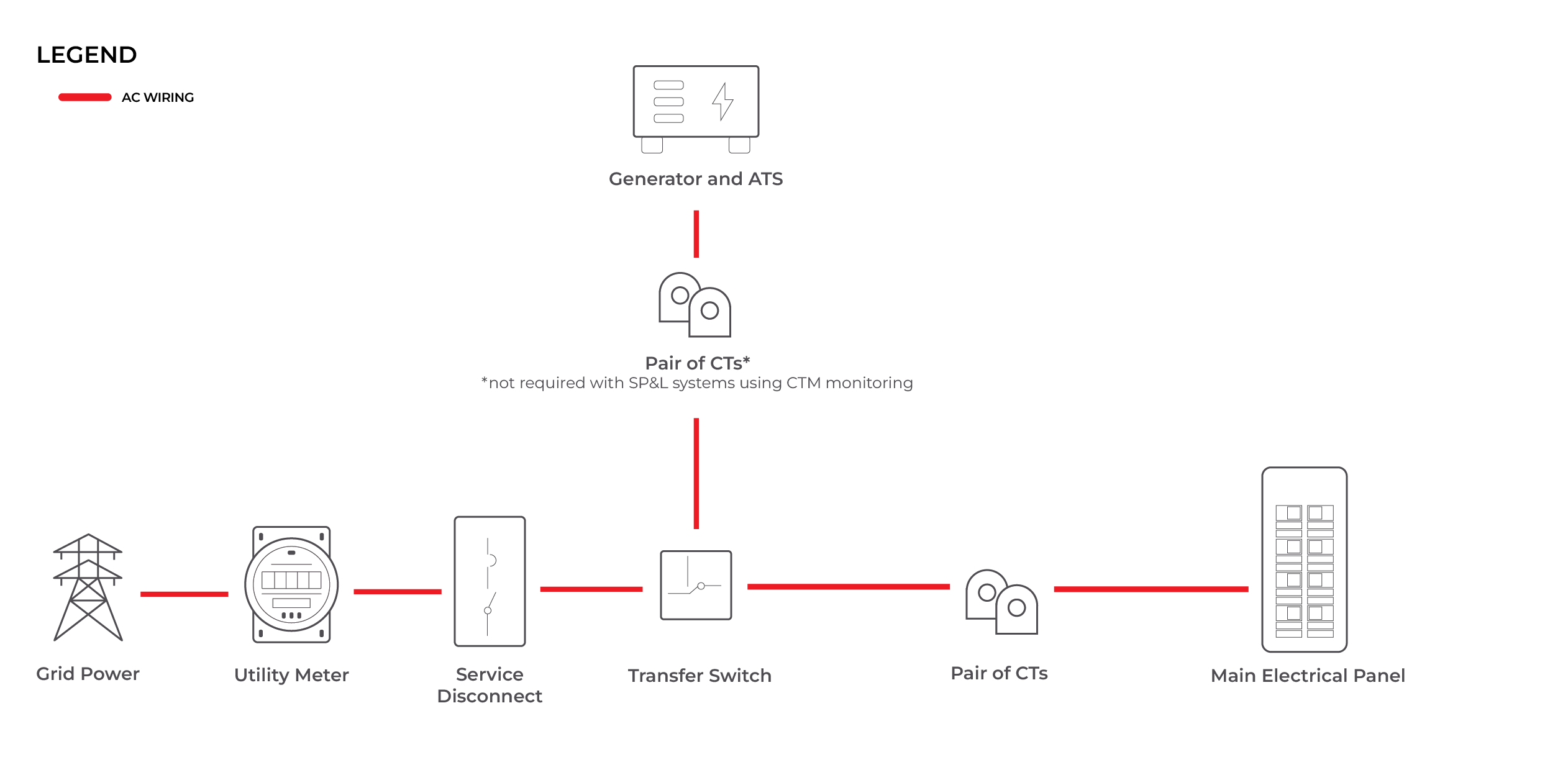
NOTE: Systems with the generator and ATS connected before the main panel can be configured using a single CTM and pair of CTs for monitoring where both the grid feed and generator connect to the main panel.
Supported Configurations:
- The panel backed up by the generator can be the main panel (generator/ATS before main panel) OR a sub-panel/critical load panel (generator/ATS after main panel)
- Systems may be non-budgeted (generator sized to provide power to all loads in the backed-up panel, no load shedding required upon grid outage) OR budgeted (generator not sized to support all loads in the backed-up panel, load shedding and flexible load management will be used upon grid outage)
- Systems may be configured in the Savant Power & Light app using a Savant Power Director, OR via Blueprint using a Mac Host or HST-DIRECTOR-01
- A Savant Controller (SSC-xxx) with a GPIO input for connection to the ATS is required in Mac Host systems
- A Panel Bridge controller is required in Mac Host systems using Current Track Modules (CTMs) for monitoring
System Overview Examples
The diagrams below show simplified system architecture examples for generator-only backup with the generator and ATS before the main panel, and generator and ATS after the main panel, backing up a sub-panel. Only the CT position is shown - CTs must be connected to Current Track Modules or to an SEM-2015 depending on the monitoring method in use.
Generator and ATS Before Main Panel
Generator and ATS After Main Panel (Generator Backing Up Sub-Panel)
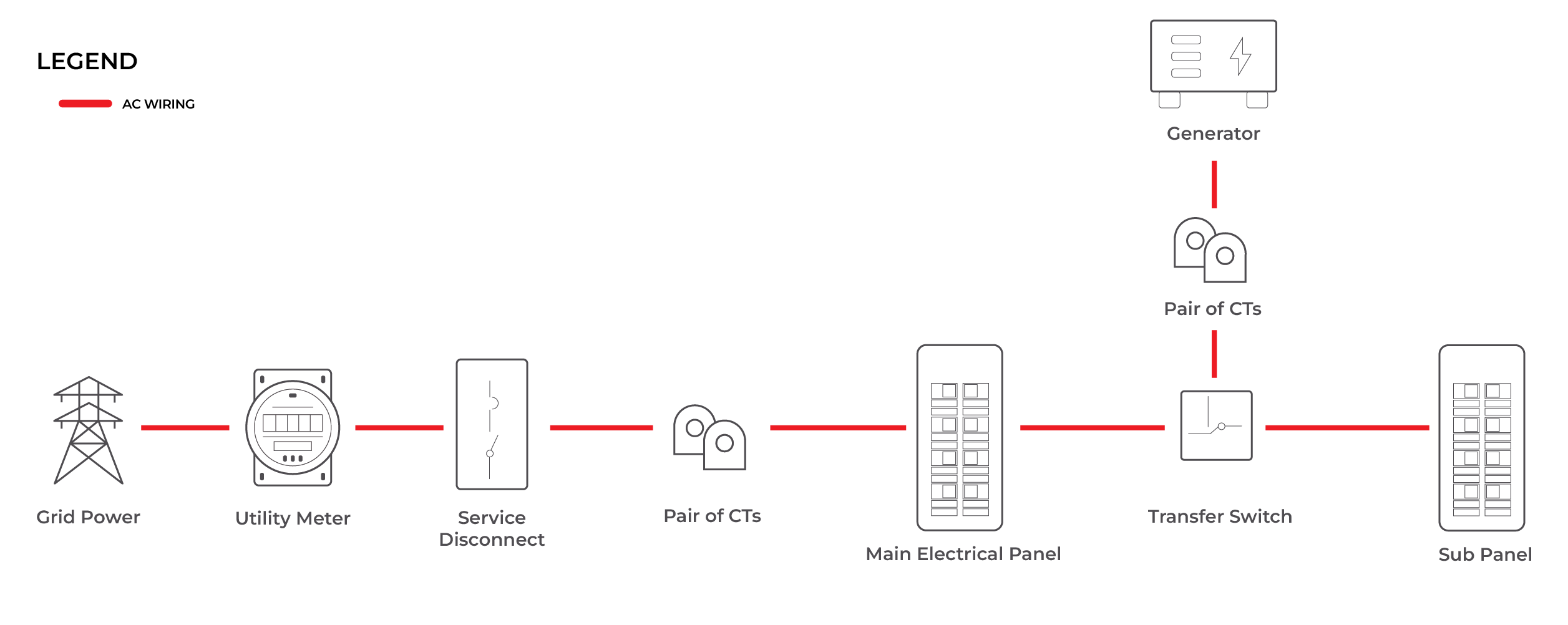
Monitoring Using Current Track Module(s): Current Track Module is installed in the Main Electrical Panel and a pair of Current Transformers (CTs) are clamped around the wires between the Main Electrical Panel and the Transfer Switch. A second CTM is required, with a pair of CTs between the generator and transfer switch for generator monitoring in any system with the generator and ATS connected after the main panel (backing up a sub-panel).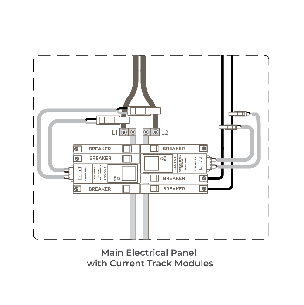
Monitoring Using SEM-2015: A SEM-2015 is physically installed next to the Main Electrical Panel and has VT and a pair of CTs clamped around the wires between the Main Electrical Panel and the Transfer Switch. A second pair of CTs are required between the generator and transfer switch for generator monitoring.
System Configuration
Following physical installation of all equipment in accordance with product documentation and the system guidelines described above, follow the steps below to configure the system for the monitoring method installed (CTM or SEM-2015) using either the Savant Power & Light app or Blueprint.
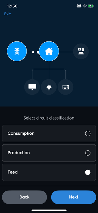
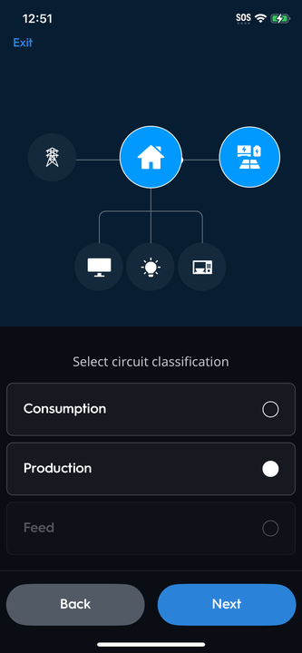
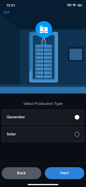
Savant Power & Light App Configuration (Director Only)To configure a Power Director system with generator-only backup power source using the Savant Power & Light app, follow the steps below for the monitoring method in use on site (CTM or SEM-2015). Note that these steps assume initial Smart Panel setup and module pairing have been completed. Refer to the Savant Power & Light App - Initial Smart Panel Setup Guide for more information. |
Add Generator as Power Source
|
Configure Monitoring with Current Track Module(s)
|
Configure Monitoring with SEM-2015
|
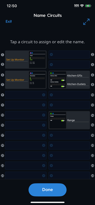
Create Off Grid Scene
|
Blueprint ConfigurationThis section assumes basic components have been installed and added to the Blueprint layout such as the Host, Network Switch, and other devices. Follow the steps below to configure a generator with monitoring using Current Track Modules or an SEM-2015 in Blueprint. |
Configure Monitoring with Current Track ModulesConfiguring a Savant Smart Panel with a generator-only backup power source using Savant Current Track Modules (GPM-xxSEM) requires:
|
Configure Monitoring with SEM-2015Configuring a Savant Smart Panel for generator only as a backup power source using an SEM-2015 requires two (2) sets of Current Transformers (CTs). One pair of CTs is landed on the Feed to measure Live Consumption when energy is being provided from the Grid. The other pair of CTs is used to measure Live Consumption when energy is provided by the generator.
|
Configure Energy Manager and Off-Grid SceneIn systems utilizing Savant Power Modules for flexible load control / circuit management, complete the steps below to configure at least one Off-Grid Scene. This section can be skipped for systems with no controlled circuits. The Energy Manager is disabled when the No Controlled Panels option has been enabled within Microgrid Controller settings for the Generator.
|
Appendix: Generator Profile Settings
Savant Power & Light App
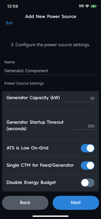 | Generator Capacity (kW) | The rated capacity of the Generator |
| Generator Startup Timeout (seconds) | If power is not measured after the timeout period, a notification will be pushed that the Generator has failed to start. | |
| ATS is Low On-Grid | Enabled: The GPIO (from Director) detecting grid state expects a normally closed contact on the ATS when On Grid. Disabled: The GPIO (from Director) detecting grid state expects a normally open contact on the ATS when On Grid. | |
| Single CTM for Feed/Generator | Enable when using one (1) Current Track Module for Whole Home Backup Configurations with a generator as the only power source. | |
| Disable Energy Budget | Enabled: Requires that the Generator can support the entire load of the backed-up panel while Off Grid. Disabled: Either the Generator cannot support the entire load of the backed-up panel while Off Grid and load management will be required, or load management is desirable. |
Blueprint - Microgrid Controller Settings for Generator
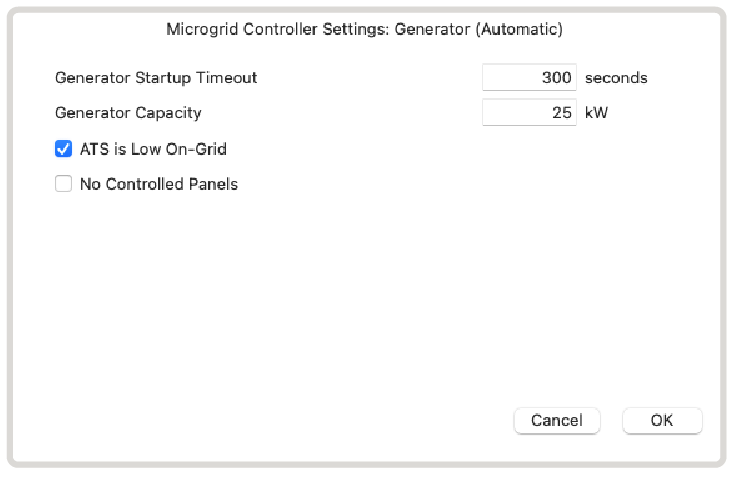 | Generator Capacity (kW) | The rated capacity of the Generator | |
| Generator Startup Timeout (seconds) | If power is not measured after the timeout period, a notification will be pushed that the Generator has failed to start. | ||
| ATS is Low On-Grid | Enabled: The GPIO detecting grid state expects a normally closed contact on the ATS when On Grid. Disabled: The GPIO detecting grid state expects a normally open contact on the ATS when On Grid. | ||
| Single CTM for Feed/Generator | Enable when using a single CTM and pair of CTs to monitor both the grid feed and generator in systems with generator connected before the main panel. | ||
| No Controlled Panels | Enable when load management will not be used (requires that the generator be sized to support all loads in the backed up panel). Note that enabling this option will disable Energy Manager and the creation of Off Grid Scenes. | ||