Savant Power System Deployment Guide - Meter Zero Mode
Document Date: November (Updated) 2025
| Overview |
| Equipment |
| Director to Inverter Wiring |
| Install Current Track Modules & CTs |
| Savant Power Storage App |
| Savant Power & Light App |
| Appendix A: Acrel Meter |
| Appendix B: System Diagrams |
Overview
This document describes the physical installation and app configuration required to enable Meter Zero Mode for a Savant Power System. It is intended to be read and followed alongside standard installation documentation for the products in use on site.
In Meter Zero Mode, the Savant Power Storage System calculates the total load reported from the feed of the main panel. The Savant Power Storage inverter then attempts to use solar or battery power to offset the load of the main panel until the state of charge falls below the Backup Reserve State of Charge.
NOTE: An Acrel Meter can also be used for Meter Zero Mode in place of Current Track Modules. For more information, see Appendix A: Acrel Meter
Equipment
The following equipment is required to support Meter Zero Mode within a Savant Power System using a Director:
- Director (1)
- Savant Power Storage 20 or 50 (1 or more)
- Current Track Module(s) (1 or more)
- Current Transformers (2)
- RJ485 CAT5 or Higher Ethernet Cables (1 per inverter)
- CAB-INVBATT-02 Connector (1 per 2 inverters)
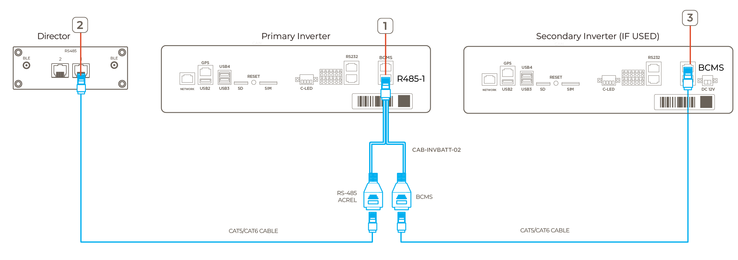
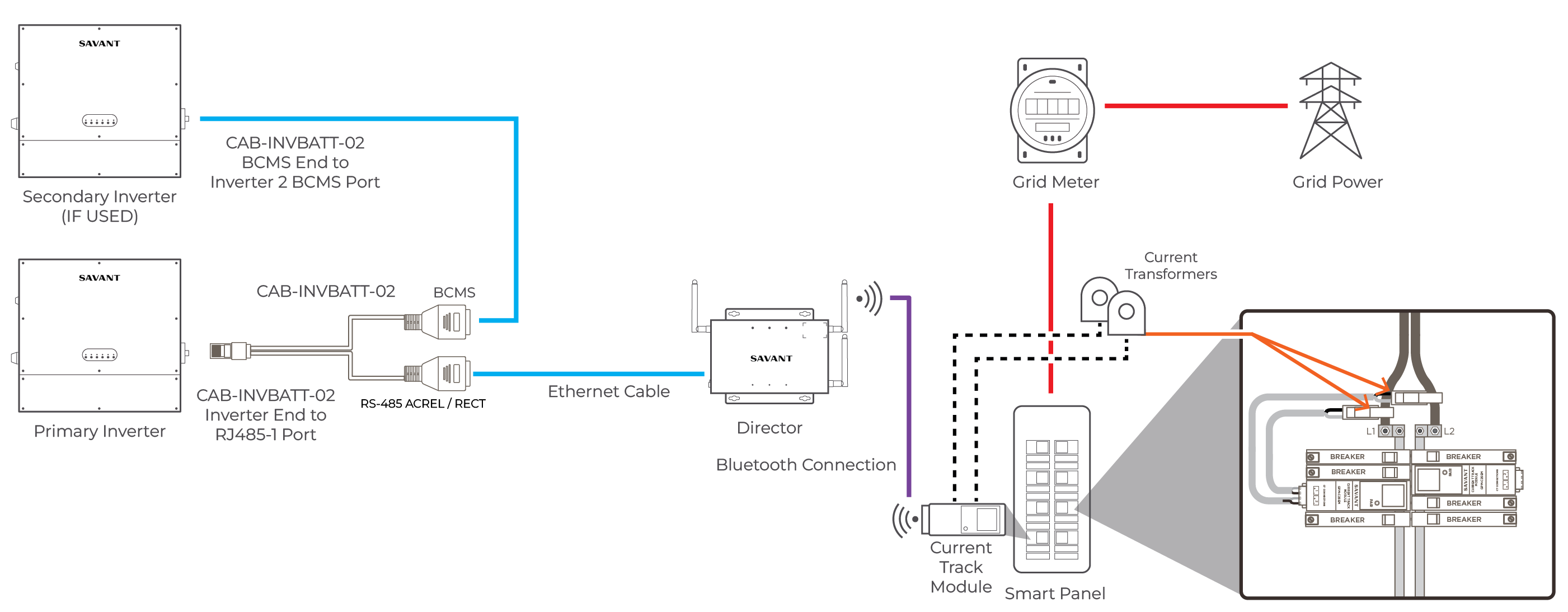
Director to Inverter Wiring
- Insert the INVERTER male connector end of the CAB-INVBATT-02 cable into the RJ485-1 terminal of the primary inverter
- Use an Ethernet cable to connect the RJ485 port of the Director to the RJ485 / ACREL port of CAB-INVBATT-02 connector
- (Shared Battery Only): Connect the BCMS port of the CAB-INVBATT-02 cable to the BCMS port of the secondary inverter
Install Current Track Modules & CTs
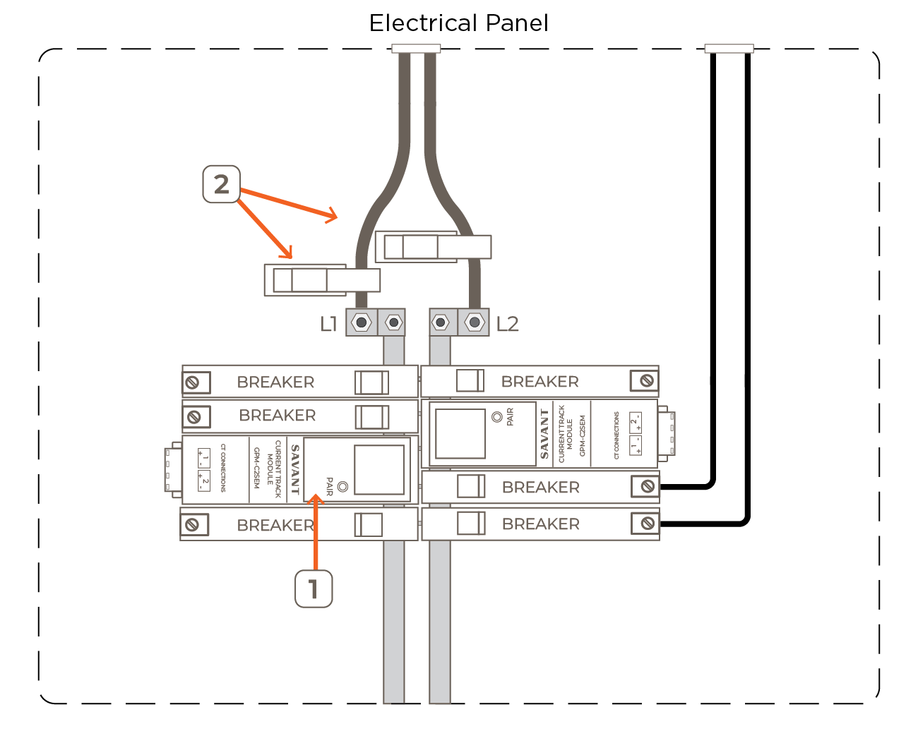
- Install the Current Track Modules (CTM) into the appropriate spaces within the Smart Panel. For more information on installing a Current Track Module, see the relevant Current Track Module Quick Reference Guide listed within Savant Power System - Product Quick Reference Guides
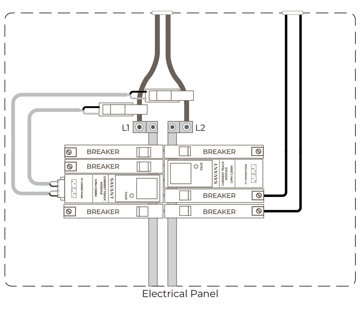
- Place Current Transformers (CTs) around L1 & L2 between the Grid Meter and the Smart Panel
 IMPORTANT NOTES:
- CTs 150A or higher must be oriented with the arrow facing toward the power source
- For added security, wrap a cable tie around the CT or run the tie through the loops on the front
- Route the twisted black and white wires from the current transformer panel to the Current Track Module CAUTION!: Ensure wires do not directly come in contact with a live bus bar or terminal
- Remove the terminal block from the rear panel of the module
- Strip back the insulation of each CT wire to 1/4 inch (6.5 mm). Install the wires as depicted in the image below: IMPORTANT NOTES!:
- When using SEMFLEX-2500A CTs, The POS wires are brown and the GND are white
- The bare/shield wire is not connected and must be capped or taped off
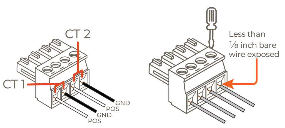
- Turn the screws clockwise until the silver crimps tighten around the wire, tugging on the wire slightly to verify the wire is installed securely
- Plug the terminal block into the appropriate port. Below is a complete wiring example:
Savant Power Storage App
This section describes configuring the Savant Power System for Meter Zero using the Savant Power Storage app, additionally to the configuration required within the Savant Power Storage (SPS) App Setup Guide
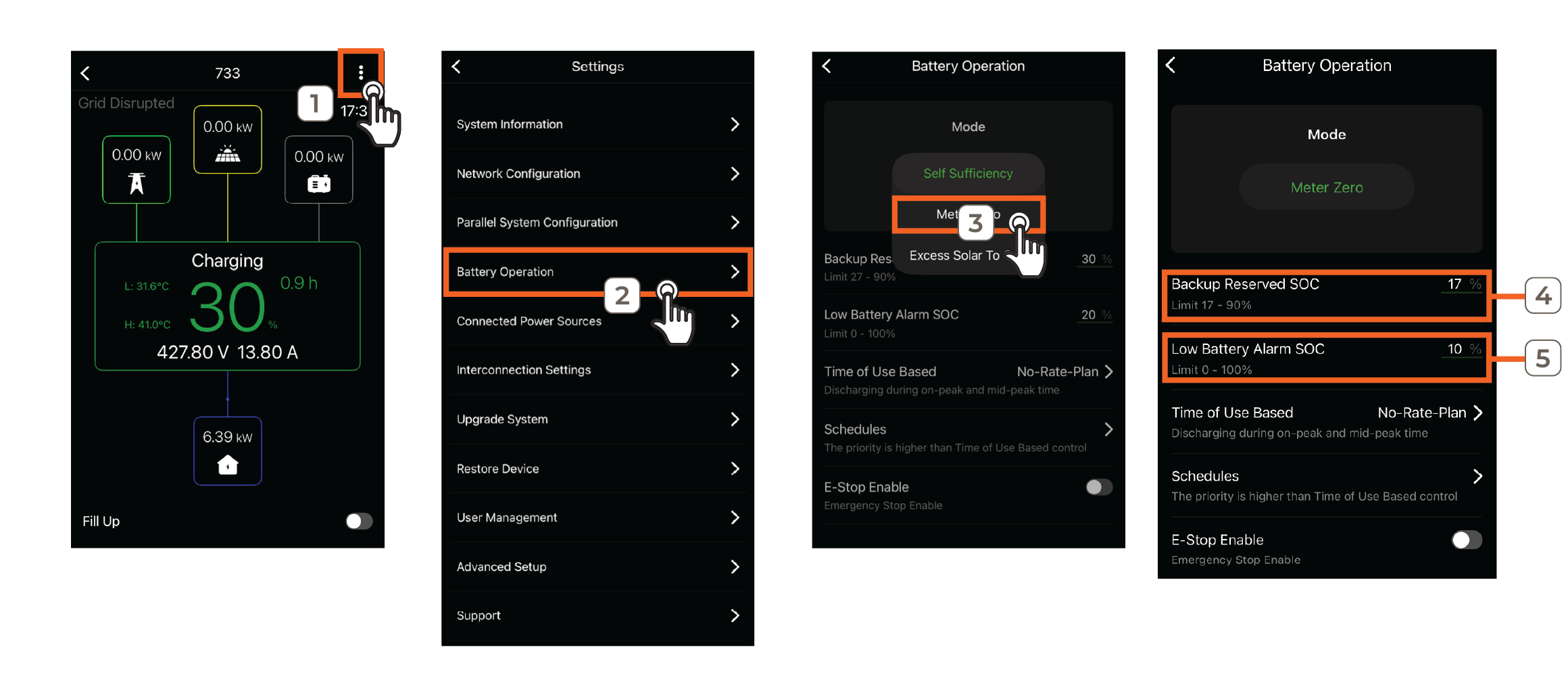
- Open the Savant Power Storage app and tap the ... icon in the top right corner to access Settings
- Select Battery Operation
- Toggle Mode to Meter Zero
- Set the Backup Reserved SoC percentage that the inverter will begin accepting power from the grid to supplement the Power Source
- Enter the Low Battery Alarm SoC percentage that will trigger the alarm
![]() IMPORTANT!: When deploying Meter Zero functionality using a Director, continue deployment from the beginning of the Savant Power & Light App section
IMPORTANT!: When deploying Meter Zero functionality using a Director, continue deployment from the beginning of the Savant Power & Light App section
Savant Power & Light App
Savant Power & Light app configuration is also required when using a Director. This section describes configuring the Savant Power System for Meter Zero within the Power Source section of the Savant Power & Light app, independently of other SPL configuration steps.
Setup Current Track Module
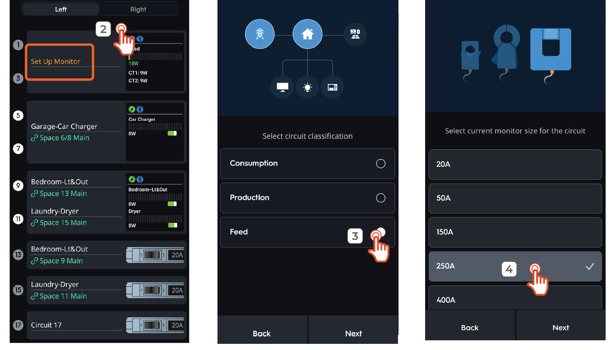
- Tap an empty space within the Smart Panel in the Savant Power & Light app and add a Current Track Module
- Touch Set up Monitor
- Choose the Feed circuit classification type
- Select the amperage of the Current Transformer and tap Next
Configure Power Source
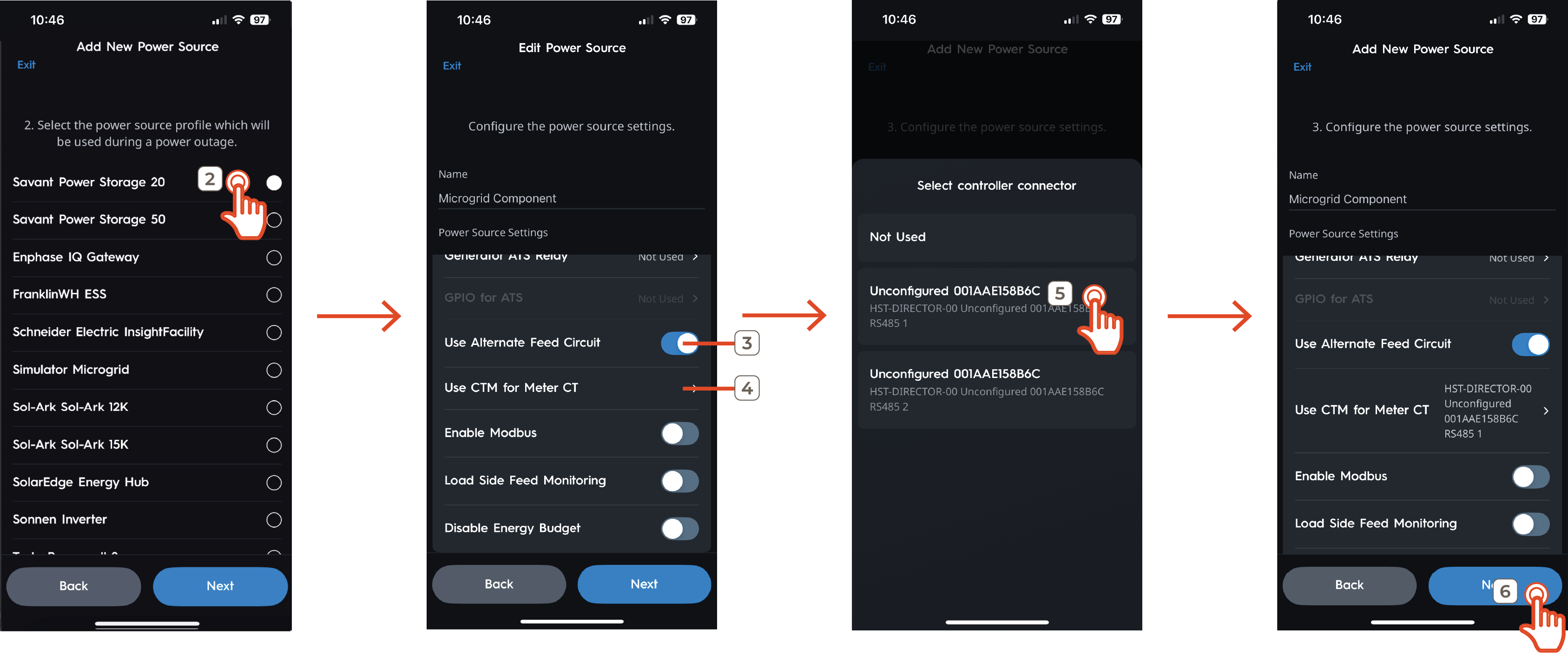
- Tap the plus sign to create a new Power Source and choose the Power Source type or edit an existing Power Source
- Select the applicable Power Storage 20 or 50 Power Source profile and tap Next
- Enable Use Alternate Feed Circuit to allow SPL configuration of the source used to transmit feed data to the Director
- Tap Use CTM for Meter CT
- Select the Director
- Continue Power Source configuration according to Savant Power & Light App - Adding Power Sources
Once the power source is configured, Meter Zero deployment is complete.
Appendix A: Acrel Meter
Equipment
The following equipment is required to configure a Savant Power System for Meter Zero Mode using an Acrel Meter:
- RJ485 CAT5 or Higher Ethernet Cables (1 per inverter, see Power Storage 20 or 50 accessories kit)
- CAB-INVBATT-02 Connector (1)
- AB-INV485 ACREL Meter Connector (1)
- ACREL Meter (1)
- 15-amp, 240 volt, two-pole breaker (1 Placed on Not Backed-Up Load Center)
Installation
Complete the steps below to install an Acrel Meter for Meter Zero monitoring. Then complete the Savant Power Storage App Setup section of this article.
- Insert the male connector end of the CAB-INVBATT-02 cable into the RJ485-1 terminal of the primary inverter
- (Shared Battery Only): Connect the BCMS port of the CAB-INVBATT-02 cable to the BCMS of the secondary inverter
- Connect the RJ485 / ACREL port of the CAB-INVBATT-02 connector to the AB-INV485ACREL RJ485 port
- Connect the AB-INV485ACREL to the RJ485 / ACREL end of the CAB-INVBATT-02 connector to the Acrel RS485 pins using a terminal block as follows:
Ethernet Cable Pinout RS485 Communications Port Pin 7 A+ Pin 8 B- 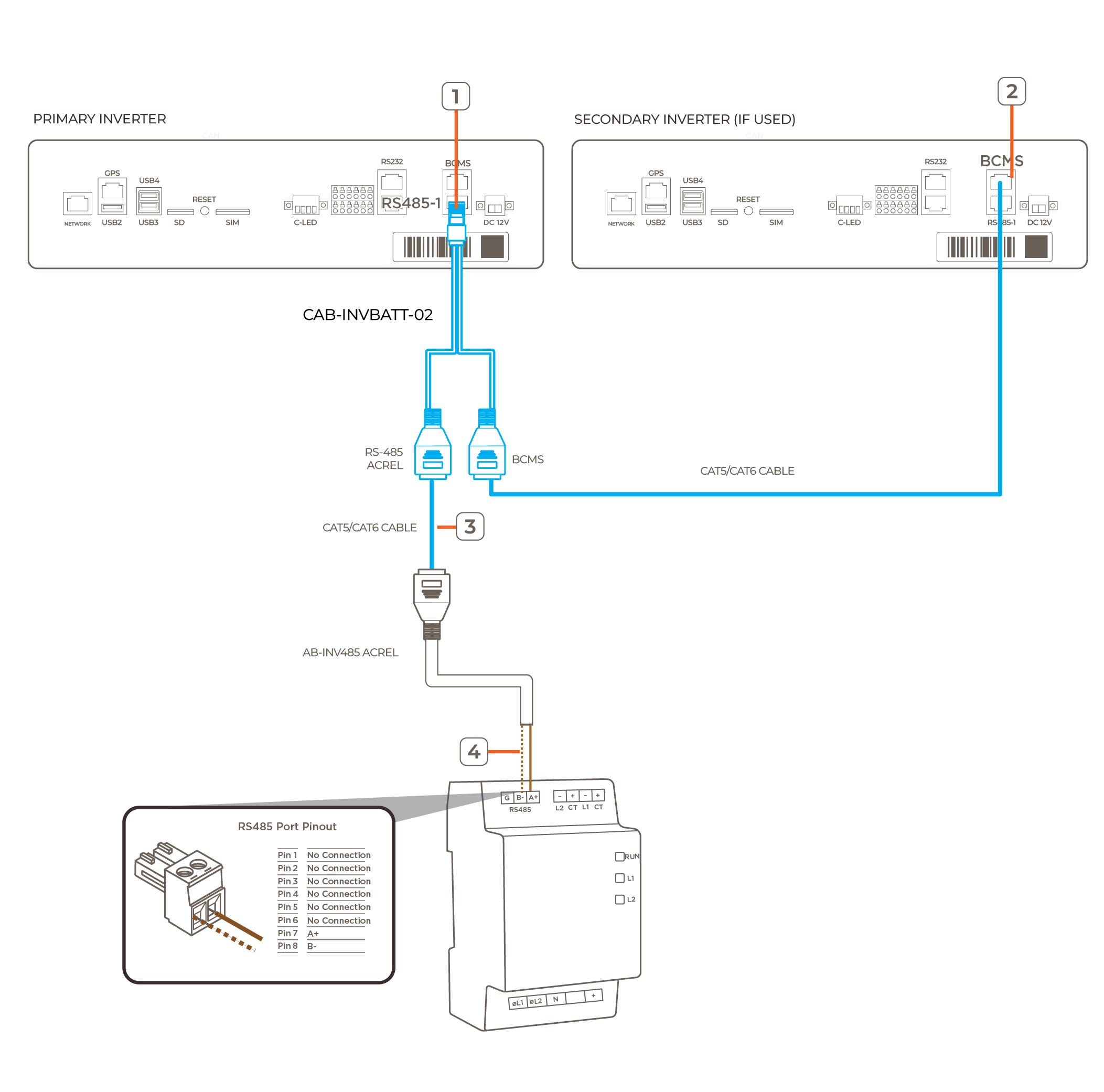
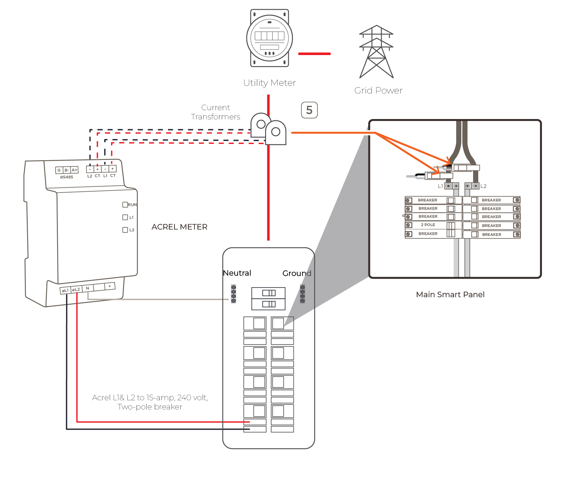
- Wire Current Transformers from the CT ports of the Acrel Meter around both L1 & L2 feeds before the main Smart Panel. Connect CT1 (black sleeve) to Line 1 and CT2 (red sleeve) to Line 2 IMPORTANT!: The arrow on CTs must point towards the loads on the non-backup load center for accurate measurement
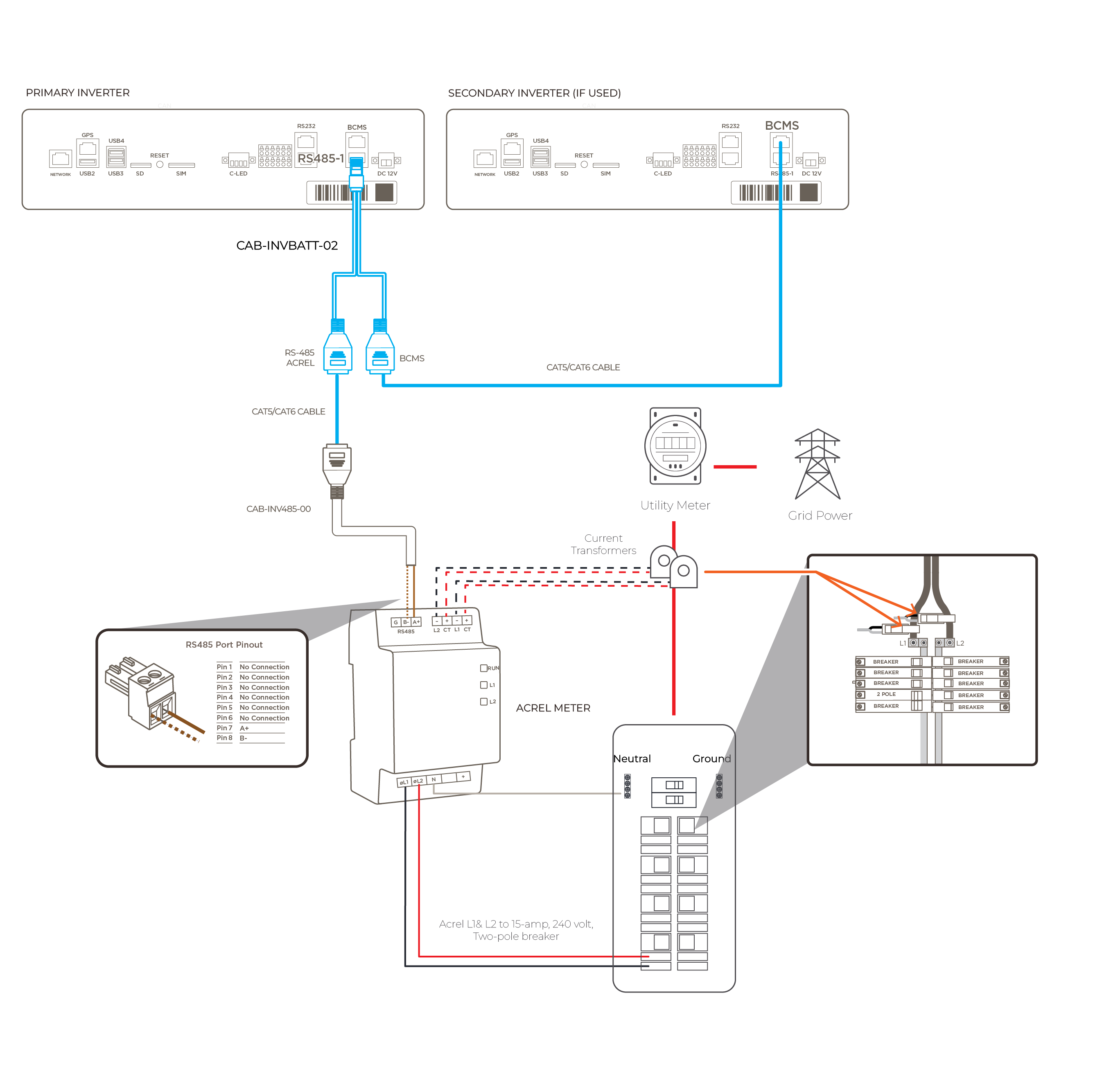
- Connect the 15-amp, 240 volt, two-pole breaker in the non-backup load center to L1/L2/N of Acrel meter. The diagram below represents a completed Acrel Meter Zero system IMPORTANT!: The phasing powering the meter must match the CT placements for each phase
Appendix B: System Diagrams
Savant Power Storage System with Director & Meter Zero (Current Track Modules)
Savant Power Storage System with Meter Zero (Acrel Meter)